As many of you know, my modelmaking comes in fits and starts. On personal projects, that usually means 1 or 2 months of modelling a year, and that's it. On BRM projects, it is usually more consistent year-round, however lately I've fallen behind by about 4+ months due to a myriad of reasons; S.A.D being a big part of it, but also struggling with a build that I initially thought would be straight-forward that turned out to be anything but! Instead of moving onto another project and coming back to it, I ended up in a weird non-productive mojo-less limbo; frustrated by the kit in question, whilst also struggling to rein in my expectations and perfectionism. Thank goodness the folk at BRM are so understanding, and that I had plenty of layout photography work to do for them instead!
So anyway, why a sudden update now? Well, mostly it's thanks to the lovely Carol Flavin, who, despite having surgery and other challenging circumstances, has made great progress on her new 009 layout; the 'Harland Light Railway'. I'm very fortunate in that we have regular communication via Twitter, and she always sends me photos, updates, and videos of her modelling and such. Her surprisingly quick construction of the HLR so far, as well as her encouragement, made me realise that what I really needed was a small break, and to start on a new project for myself to get me out of my creative rut. Combined with the lovely sunshine recently, and finding a huge roll of paper which I was free to use, I felt it was time to turn my latest version of Bramble's Boatyard into a more tangible form!

Above: OK, so it's not the most visually stimulating photo... however, this image does show physical progress for the first time in ages! My studio is pretty tiny, (all that's out of shot is my desk and chair), so space is tight. Still, to my surprise I could fit all 2.6m of the scenic portion of the layout into my studio. Good to know!
Above: Annoyingly, the paper is something like 445mm wide, not 500mm; so three sheets were needed to get the full 1m width of the layout at its' widest point. Time to head to the lounge where there's more space. Here, I'm using Dad's big builders compass (there may be a more technical term, but this'll do!) to mark the curved ends out. It's not exactly a precision tool, but it does the job... more or less!

Above: Before we go any further, let's remind ourselves of what the last version of
Bramble's Boatyard looked like. I've just realised that the above plan is actually out-of-date as the three-way point has been removed and replaced with a medium left-hand point, and the curving siding leading from the bottom route of the three-way has thus now gone. Still, that's about the only change, so it'll do until I can update it.
I should probably note at this point that my original design for the front of the layout was to be a smooth curve that, more or less, got exponentially tighter towards the ends (as you can see in the plan). With no clue how to really tackle that in a simple manner, I opted for a simpler approach when marking it onto the paper mock-up. The sharp curved ends are approximately 817mm radius (the radii and its centre points worked out from the XtrkCAD file), and the last 600mm towards the centre of the layout (at it's widest point of 1m) is now simply connected with a straight line; thus there is a very slight 'point' to the centre of the layout.

Above: The layout looks huge in this tiny room, but I bet it won't when I eventually take it to an exhibition hall! In any case, with the shape marked out, it was time to find the points and random bits of track I had bought many, many years ago for a failed layout, and see if the XtrkCAD plan fits...
Above: ...and it certainly does! I've taken these photos because it nicely shows off the lovely flowing trackwork. You'll be hard-pressed to find any parallels here; especially against the baseboard edge. Do note though that the track by the brick bridge should curve towards the front edge slightly (i.e. in the right photo, the track nearest the camera should be bent slightly to the right as it comes towards me).
Now, forgive me, but at this point I need to go on a slight diversion - we'll get back to the mock-up in a bit...(It'll make sense why soon enough!)
Many months ago, I started designing the baseboards for the layout. I don't think I ever posted them (as they were never finished), but they looked like this:
Above: Yes. It is a little on the overengineered side! The craziest part about it though is probably the criss-cross diagonal struts (dark/navy blue). These fit into the weight-saving holes of the strengtheners (yellow). Now, although these are half-lapped so that they just slot together to form the X shape, they would still be a pig to install as they would need to be slotted through all the strengtheners before ANY assembly/gluing can take place. I imagine that even an octopus would have trouble holding that many parts together! I did make sure the holes were large enough to fit two of the cross strut pieces atop one another so that you can actually get them in, but the rest of the practicalities were clearly lost on me at the time...

Above: Continuing the same design, we now have the lighting rig, backscene, and fascia installed. As the image says, this is the exact same design I used for Sandy Shores, albeit with multiple hinged arms this time due to the size of the layout. The pelmet, by the way, is in two separate halves, and I suspect the backscene would be, too.
Just for completion sake, the colours relate to the following:
ORANGE = 3mm ply (if it'll bend that tight, if not, it'll be 5mm 'bendy' plywood)
CYAN = 3mm plywood (same as orange, but I chose a different colour so you could see them!)
ALSO ORANGE = 21mm x 21mm quadrant mouldings (to ensure the yellow cross struts are perpendicular)
YELLOW = 9mm plywood, with 65mm diameter holes to save weight
GREEN = 12mm plywood (used on the straight perimeters of all boards)
RED = 18mm plywood
PINK/PURPLE = 18mm x 44mm PSE softwood
NAVY BLUE = 18mm x 28mm PSE softwood
WHITE = 34mm x 34mm PSE softwood
DARK GREY = 6mm plywood
Now that I'm back after many months, and with a fresh set of eyes, clearly there are too many materials, it's too complex, and probably over-engineered! But there's also another issue I thankfully spotted...
Above: Whilst I did spend a long time moving cross-braces (yellow) and board joins to ensure they would not get in the way of points and their motors, for some reason I had overlooked the bridge and the traverser. Both of these would span baseboard joins (marked with the red dotted line). Whilst the swing portion of the bridge is fine, the fixed span certainly wouldn't be.
Thus, a perfect opportunity to use the mock-up to approach things from a different angle...
Above: ...and I soon realised that I could, instead of splitting the layout into 4 boards, split it into 3 (note the cyan lines); thus bypassing the problem of the bridge (on the left) and traverser (marked in pink) being on a board join. (P.S. note that I forgot to add the top right sidings in the earlier photo, but have included them in this one.)
The only downsides I see are that the board sizes are slightly bigger, and that we have one pair of stackable boards and a larger central board; instead of 2 sets of matching boards that can be stacked. Still, fewer board joins is always a big bonus, and more importantly, the bridge and traverser mechanisms won't have to be more complicated than they need to be; nor removable! The large central board can be transported with a plywood lid, so the fact it can't be stacked is of little consequence, I feel.
So, let's see what we can do for a new baseboard design. The first area I started with was the middle board as that is the easiest one. But that's when I realised something that would make it even easier...
...are slight curves/angles worth the hassle?
Earlier, I mentioned that instead of having one continous and exponentially curving fascia on the front of the layout, I would instead have a fixed radius curve on the two outer boards, whilst the central board would feature a very slight point in its centre. Creating this in Sketchup wasn't particularly difficult, but there were a few approaches I could take:
Above: Three methods that I considered when trying to work out how to produce either an angled or curved fascia. (Click to open larger version). OK, so they're easy to make in Sketchup, but what about the real world? Well, for those wondering how on earth you'd cut angles so minimal, and also make rebates that are angled, the answer lies in this:
Above: This nifty bit of kit is a cross-cut mitre saw (you can just see the metal saw blade under the main blue body/motor casing). Not only can you create easy angled cuts, but you can also mitre/bevel them by tilting the blade left and right and using the scale at the back (see inset). Essentially, you can create any angle with ease, and you can even use it to create trenches/rebates (and angled ones at that!). The perks of having a carpenter dad with useful tools!

Above: Dad thus showed me the ease at which you can create an angled rebate; which would be needed to join the yellow cross-struts to the angled green front edge. Imagine the softwood (going vertically in the photo above) is the 12mm ply baseboard edge from my 3D design, and the horizontal (ish) bit of wood is a 9mm (yellow) cross-strut. Using a set-square, we can see that even a tiny angle like 1.5 degrees (or even smaller) is easily done with the cross-cut mitre saw. The saw, by the way, also has a depth stop; so you can be sure the cut is always at the same depth; perfect for trenching/rebate work like this.
However, one thing then dawned on me. As nice as it is to be able to do all this, is it really necessary? Well, no! I decided that the (admittedly satisfying) visual flow gained from creating a baseboard that is pointed or curved to create 30mm of extra width in the middle, doesn't really justify the added complexities and time taken to produce it; even if you have the tool(s) to do it fairly easily!
Even though this is a personal layout project, with my BRM practical how-to hat on, I also thought about "How would other people create this with minimal tools at their disposal?". The answer would be... "good luck!". OK, so I guess you could use a handsaw at an angle, but that's a PITA, and much harder to achieve accurate, consisent results!
So, long story short, I did away with it entirely, and now the baseboard will be two standard curves joined by one, standard, square, straight board. Simple! Sure, it would be nice to have a lovely flowing baseboard all the way along, but for once, I'm letting the practical part of me take precedent instead of the design/creative side. It must be a full moon!
With that in mind, let's carry on with the new baseboard design:

Above: Much simpler! Though, to be fair, I haven't yet included the lighting rig supports, but unlike the old version, these will not be in the way of the diagonal strengtheners. Note the white cylinders embedded in the cross struts in the new version - these were later used to 'punch out' the weight-saving holes in the 3D model. Anyway, we are still using 12mm (green) plywood around the outside and 9mm (yellow) cross-struts complete with softwood quadrants to create a rigid board. However, all the various types of diagonal members have been replaced by a much simpler arrangement of 9mm plywood crosses underneath; one for each board. Another thing to note is that I've reduced the depth of the board from 150mm to 120mm; which is why the new baseboard looks longer.
In any case, let's look at the design a little closer:
Above: This screenshot shows one of the cross-struts being put into position. Note that in reality the quadrants would be glued in place afterwards, but you get the idea. I've moved two of them out of the way so that you can see the half-lap in the two cross-struts that allow them to interlock; the slots of which are easy to produce with a router. Note also the rebate in the green side on the left between the two quadrants.

Above: A close-up, exploded diagram showing the construction detail of the area around one of the two front baseboard joints. Hopefully it's fairly self-explanatory!
Above: The 9mm plywood crosses underneath are also rebated like the ones in my old design were, however, by using a thinner material, we can actually put these on after we've finished the main frame instead of trying to thread them through the cross-struts whilst also holding 20 components at once! However, to achieve a flush finish, a slight design adjustment would be needed:
Above: Instead of simply nailing the crosses to the bottom, ensuring that they would be flush with the bottom of the frame requires 9mm to be 'cut off' from the bottom of all the cross-struts and quadrants. The kind of thing that's much easier to do on a 3D model than it would be to do retrospectively in real life! This is why I find CAD work so invaluable.
As a slight aside, whilst I could now make things neater by not rebating the bottom 9mm of the green sides (now that the yellow cross-struts no longer reach the bottom), I decided that it's not worth the effort; it's much easier just to router the rebate/trench in one smooth motion right the way down the width of each piece, than have to stop 9mm from the end each time.
Above: Sometimes you forget about the basics; especially after a long break! Here, I've split the layout into two 700mm wide boards and a 1000mm wide board; however note that the first red circle denotes that the bridge mistakenly spans two boards. I've also equidistantly spaced all the cross-struts; however, that's not always the optimum position for them as point motors will get in the way, as evidenced with the second circle! This calls for a partial rethink...
...I say partial because I'm not going to change the width of the boards; it would cause more problems than it would solve - having two identically shaped boards is more important here, and no other width would really work for other reasons.
The solution is simple. Shorten the bridge, and adjust the cross-strut spacing. Let's start with the latter:
Above: To avoid the curved point tiebar on the far right of the plan, the spacing of the cross-struts has been adjusted; so that they are no longer spaced evenly. Additionally, another row of them has been added. The reason for this is twofold:
- Firstly, the new spacing would otherwise create a large gap between the fascia and next row of cross-struts; thus being a potential weak point - especially with the curved fascia potentially trying to push the ends apart. Rather than align the new horizontal row with the first vertical cross-strut. What I've done is line it up more-or-less half-way between that and the end of the board. My reasoning is that it will provide more support points to hold the fascia in place.
- Secondly, one of the original rows previously supported the far anchor point of the curved fascia of both outer baseboards - whilst I could have kept a short section there, it's easier just to add a quadrant moulding there, which should still give enough support. It's not something I'm too worried about because we've also got the yellow X underneath that anchors that corner nicely at the bottom. In any case, if it looks like it will create a weak point, I can always 'beef it up' during assembly.
Something to note is that I've carried this new spacing across to all of the boards. That will make cutting out each half-lap in the cross-struts easier as I won't have to keep measuring different spacings (and don't worry, I checked that it won't impact other point motor positions etc.!).
Above: The bridge shortening is slightly harder to see, so I've annotated a couple of photos I took during the process; which are taken from roughly the same position (more luck than judgement!). Using the green dotted line to represent the baseboard join, we can see that the original bridge length would've sat directly on this join. As that is the pivot end of the swing bridge, that isn't going to work.
The lower photo shows the new design; the span has been shortened, as has the arch; which I've actually based on one I built for The Old Road (remember that project?!) - hence why it's suddenly become much wider as well. It does look a bit odd, so I'm not sure if I'll keep it (and besides it's a very old scratchbuild, so it needs a bit of work to bring it up to par!).
This bridge took me a while to get right with regards to the swing span - I realised that my original design had the pivot as close to the end as possible. However, looking at what few examples I could find online, the pivot is clearly brought in towards the centre a bit so that you can have enough space for counterweights. Makes sense! I suppose I should really move it even closer towards the centre, but that would narrow the navigational width even further than I already have.
The only other thing I'm not 100% happy with is that the river now has quite a pronounced curve again on the far side due to the alterations made. I'm hoping it's not too tight for small boats to negotiate! I may be able to move the brickwork's kiln slightly to the left to ease the curve of the river, but it's already a fairly compact scene... we'll see.
Above: The full plan crudely drawn onto the paper; don't study it too closely! Ideally, I'd just print off the XtrackCAD file, but that would require a lot of printed A4 sheets, and a lot of time spent taping them together!
Above: Taking a closer look at the right-hand end of the layout, testing shows that we can just about fit in a class 03, two vans, and a brake van. My new plan is to use the headshunt to store the brake van during shunting maneouvres, rather than the loco shed road. The traverser behind the loco can indeed fit the well wagon and 03. Just! Though this is only going to be used by the Ruston 44DS as it's much lighter (and smaller). P.S. I know the 03 is about 13 years out of period, but I now have 2 of them (a second one I got at the RMweb Member's Day). Besides, it's my layout, and I like them!
Above: A final shot for now. This shows a Q1 on the swing bridge. The actual swing span will be slightly shorter (just take off the two smaller end panels, and that's about the right length). This is a view that I think will work really well on the model, and will be a favourite photo spot, I'm sure! I'm also excited to see how this view will look with the span open and the river banks and kiln behind it visible. It should work really well with the curving river; so long as I get the backscene join convincingly subtle...
Well, that's about it for one blog entry as I've reached a point where I need more time to do work on the baseboard leg design. Besides, this entry is long enough and I've been working on it for about a week on and off! I also need to clear space again in the studio so I can return to actually doing work related modelmaking...
I hope you've found this entry interesting/informative! Do leave any comments, suggestions, or questions below!
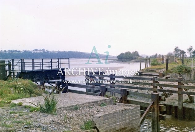
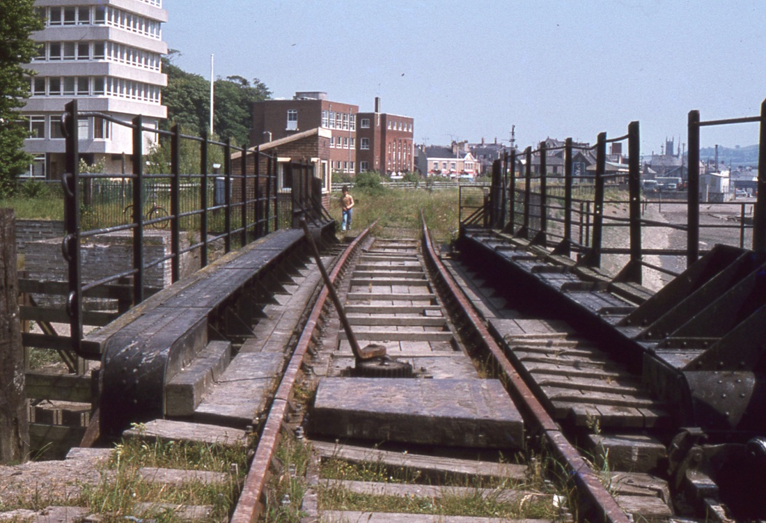
P.S. If anyone has a photo of the swing bridge that once stood near Barnstaple Town station (I've found two on the internet -
this one, and
this one, but none showing what it looked like from a similar angle to my last photo above), I would be interested to see it. I'd quite like shorter girder sides, and the views linked above of Pottington swing bridge make it look like it's perhaps a little smaller...?


James there is a smallish swing bridge in Gloucester docks link below to google streetcene
ReplyDeletehttps://www.google.co.uk/maps/@51.8629918,-2.2519633,3a,75y,103.71h,91.36t/data=!3m7!1e1!3m5!1s0i87q0F4pJ5ZILzJ_3kvgg!2e0!6shttps:%2F%2Fstreetviewpixels-pa.googleapis.com%2Fv1%2Fthumbnail%3Fpanoid%3D0i87q0F4pJ5ZILzJ_3kvgg%26cb_client%3Dmaps_sv.tactile.gps%26w%3D203%26h%3D100%26yaw%3D144.35942%26pitch%3D0%26thumbfov%3D100!7i13312!8i6656?entry=ttu
It used to have a railway across it, the trackes were still there in the mid 90s until they 'redeveloped' the place. --- may be of interest
regards
Pete
Hi Pete,
DeleteThat's a great StreetView image, thank you very much. It's unusual to be able to get (virtually) so close to one (and also be able to walk across it); so that throws up some very useful information. Looks like some weight-saving holes in the plate girder sides, and the counterweights are clearly visible underneath behind the pivot point.
Good to also see the pad on which the bridge swings open onto; again, that's something you don't often get a decent shot of.
Many thanks!
Jamie