Ever since I bought the lovely Bachmann 'Dorothea' to compliment my existing loco 'fleet' of 2 on Sandy Shores, I've realised that I need a way to run-in locomotives. (I moreso need one in OO now that I've been buying multiple locos for Bramble's Boatyard, but that's another matter entirely!).
Still, a simple roundy-roundy would be nice; but y'know what would really be nice? Having a scenic one! More specifically, using this opportunity to try and catch up on some of my BRM projects that I'm months behind on. On the cards in that respect is a pond and a windmill, so clearly I'll need a little bit of space for these, but they will certainly be perfect for a 'pizza layout' like this.
After a VERY rough sketch on the whiteboard in my studio, I set about drawing a sketch (slightly less rough) on the computer:
Above: The design calls for nothing more than a simple circuit of track, a couple of tunnels, a halt, a road, a windmill, and finally... a pond with a culvert running under the railway.
Before I had time to even finish the above sketch, my Dad had already found an offcut of ply! Happily, it could perfectly fit a 2ft/600mm diameter circle on it:
However, this is 12mm ply, so I'll be wise to reduce the weight a little. Time, once I had cut the circle itself out, to mark out where I can cut out some space-saving holes...
Above: With a 100mm wide circle around the outside, and an 80mm wide cross in the middle, I should be able to cut out four holes of decent size, whilst still allowing enough room for a solid base for the track, and avoiding losing too much structural integrity.
Above: The key to doing this as simply and neatly as possible is a router and a cutting guide. The latter, in this case, is a bit of OSB which is screwed loosely to the centre of the board. The router is then screwed tightly onto the OSB; aligning with the pivot point at a set distance to get the right radius of cut. The router and OSB can then turn on the pivot to get a perfect arc. Of course, don't forget to clamp it down, and don't cut through your work surface!
Above: After a while, the four holes were cut, and sanded to remove any splinters. All the straight lines used that spirit level in the background as a guide; it was clamped at a set distance comparable to the distance between the straight edge of the router base, and the widest part of the router blade itself.
With the simple base cut, it was time to determine what I wanted on the layout - usually I would've already planned this, but this was a rare spontaneous bit of baseboard making! My original intention was just to use a circle of first radius track (albeit actually using the old flexitrack I had from Old AGWI Rd.). However, conversing with Carol Flavin, and also thinking about what would happen if I ever took the layout to shows, got me thinking that perhaps I should add more. Also, let's not forget that I have a ton of used points from the old layout to make use of!
.JPG)
Above: To begin the design, I thought the best way was to cut some templates from paper to work out what radii might work given the space available. The tightest, 10cm radius, was the minimum recommended by others online. I then chose, pretty randomly, 12.5cm and 16.4cm. The latter was chosen because that was the maximum my compass went to! I then got the big builders compass out and marked out what Peco consider to be 1st radius in 009 - 22.8cm. Quite a lot bigger than the rest, which surprised me. (Note that radius is marked as the centreline of the track.)
Above: Clearly, the 10cm and 12.5cm radius are far too tight for this layout; even to use after the points. I say that, because for whatever unfathomable reason, there aren't curved 009 points available - so unless you're making your own curved points, you may well need some tight curves to compensate for the straight points!
Above: Adding the points into the mix (some I need to unsolder as they're attached to other bits of track from Old AGWI Rd - hence the use of some templates), we can see one potential idea. However, let's draw on this photo to give us a better idea of what my intention was...
Above: ... with a bit of imagination, I'm hoping you can see that the siding on its own on the left would be hidden under a hill that the windmill will sit on top of. The bridge in the foreground would be raised up for the road to cross the railway, with a second bridge to its right where the railway will cross a pond, before entering the platform loop. On the far side, there is a level crossing, and a tunnel shortly after. Here's what a very rushed 3D CAD model looks like:
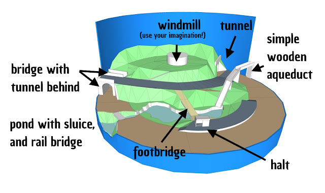
Above: A simple 3D model gives a good idea of how such a layout might look. I haven't got the scaling quite right I don't think, but it does show that it would look much better if there was a way to disguise the tunnel on the right a bit more. I also realised that the pond (which isn't as big as I would like) isn't fed by any body of water. It suddenly occured to me that one solution to 'fix' both problems (and one that was very rarely modelled) was an aqueduct -
perhaps something as seen in this photo in Wales......
Above: ...which... sort of fixed both problems. Except, it really doesn't look right to me. I should've copied the scenery across so that the tunnel is in the same place as the first 3D model, but for some reason I curved the road around. This results in less room for the windmill, and also exagerates the fact that the train just goes in a circle! Another problem is that the nice view across the level crossing can no longer be accessed as the backscene is in the way. The aqueduct, I feel, is also too dominating, though I suppose it could've been made shorter if I extended the pond all the way to the trackbed.
At this point, I was about ready to call it a day, but I thought I'd try one more thing, albeit unrelated to the previous problems. Despite the fact that I planned one siding to be hidden, another aspect I wasn't particularly keen on is that both sidings faced the same direction; which makes them boring to shunt. Now, the difficulty is that getting two standard points close to each other requires quite tight curves on a board shape this size and shape; which is what would be needed to get this siding facing the other way whilst not entering the scenic section.
Then I thought 'Do I really want it hidden?'. Well, I guess it doesn't need to be... I then considered that it might be the chance to have a purpose for the siding. Rather ironically (although this might change), I instantly thought of having a loco shed rather than an industrial use; so no shunting! In any case, that means the road needs flipping so that the bridge is on the far side of the layout. This also means rather than a train exiting a tunnel and going straight over a level crossing (which seems off to me), it goes past a loco shed first. Let's take a look at a mock-up:
.jpg)
Above: The new mock-up shows the loco shed middle left, behind the level crossing. Note that there's also now room for a water tower; which I imagined would be fed from the pond (although I've no clue if that's likely). The whole composition seems MUCH better to me; I really like how the train would exit from underneath the road bridge on the right and coast into the station; where having the platform shelter set into the embankment reduces the sudden transition from the high bridge to the low platform.
The water tower now takes the place of the original platform shelter, creating a really nice focal point mid-layout. Elsewhere, we have our view from the level crossing up to the road bridge back again. Moving around, the loco shed will only be a very small one, and the tunnel entrance will be completely covered by tree canopies and other overgrowth to disguise it a bit. The tunnel on the other wise of the hill will be incredibly hard to spot, as I will block it with a tree by the road bridge.
Let's take a look at this in sketch form:
Above: I really like this a lot! There's a lot going on, and although the track is a little closer to the edge than I would like, on the whole it's a very pleasing scene. One thing I haven't mentioned is the nice sight line from the platform, up the path, across the road, and up the path to the windmill. That should work really well. Note that I've splayed the walls of the stream/weir/sluice so that they open out towards the viewer. A culvert at the back of the pond now helps to explain where the water comes from!
However, one thing I'm not sure that quite works is the use of level crossing gates. I think the space is too narrow and there's no gap in front of the gate from which to take satisfactory photos. These will probably be removed in favour of an open crossing with simple warning signs.
As I mentioned earlier, I'm hoping the loco shed will work in the space. Although it may be easier to disguise the scenic exit with a tall industrial building with a conveyor or pipeline (or something similar),
and it will provide more interesting shunting, I think a loco shed is more fitting to the general scene. But I'm happy to take suggestions on board!
Oh, and I was going to mention the name quickly. This was a last minute decision as I suddenly realised I hadn't got a project title! My first idea was, rather ridiculously, 'Mill Hill Mill' (which was actually the name of a real windmill, apparently). My humourous side also leapt in with 'Making a mountain out of a mill hill'.. but let's not go there! Anyway, I then decided to find something else, and was then going to go for an equally funny 'Windy Miller Halt'. I realised I knew that first part from somewhere else - it hit me that it was the name given to a character in a stop motion children's TV programme! So hence why I've gone with Windy Mill Lane. A nod to that, but not a copy of! As an aside, I also mistakenly saved a file as 'Windy Hill Lane' which, to be fair, is also quite a nice and semi-humourous name.
Well, that'll do for this blog entry - watch this space for more (and yes, I will get back to Bramble's Boatyard in due course - I'm still working on the leg/lighting rig design). Do let me know if you have any bright ideas, or simply just want to leave some feedback or a general comment!

.jpg)
.JPG)
.JPG)
.JPG)
.JPG)
.jpg)
.jpg)


.jpg)

Comments
Post a Comment