Here's the final part of the brake van build!
Above: A montage of photos (taken on a recent trip) showing two types of brake handles and associated mechanisms on carriages from the Welshpool and Llanfair Railway. The green carriage (centre inset, middle top) has a much simpler arrangement visible from the outside, with the spindle driving another shaft via bevelled gears. What happens then is anyones' guess! The brown carriage is what I am guessing is a more 'traditional' arrangement based on diagrams I've seen online. The spindle is threaded at the bottom, onto which a nut and pivoted arm translates that spinning movement to an up-and-down one, and will presumably then drive a series of arms and pivots.

Above: Naturally, rather than model the easier bevelled gear approach, I chose the more complicated one! To start, the photos show that a metal bracket is needed to give enough distance from the body/bufferbeam to allow room for the pivoting arm. This is made by very lightly scoring and bending a piece of 0.010" plasticard. Unlike the photo shows, pressure was applied to the top of it when glueing, in order to make sure both 'feet' fully touch the body.

Above: The next step was to make a bracket using tiny slithers of 0.010" plasticard that will support the bottom of the brake spindle. Before the main piece was cut off to length, a hole was made using a push-pin (I didn't have a drill bit small enough), and then the two corners were cut off. Again, the photo doesn't show everything as I usually take the photo after the stage is complete - you'll want as much material around the hole as possible to prevent distorting or splitting the material, hence why it's a good idea to make the hole before cutting off the corners.
To create the two supports, miniscule triangles were also cut, and glued in place. The difficult bit was actually not glueing them in place so much as it was trying to cut out such small pieces a) the same size, and b) without them pinging into the abyss! (N.B. The cutting mat has squares measuring 0.5 inch x 0.5 inch. I never bothered to measure them until now! Sadly, inches are worthless for me - though, to be fair, centimetres aren't very useful when modelmaking either!).
Above: My first attempt at making the handle was far too big - it looks tiny when you're making it, but when you offer it up to the body...! It was made using 0.010" for the shaped base, 0.030" square rod for the handle itself, and a leftover pip from a sprue for the spindle nut cover.
Above: The new handle was made from a smaller sprue pip, which had a slot cut using a craft knife so that a piece of bent wire could sit in it and form the handle. It was impossible making a hole in the bottom of the sprue pip so that it could sit on the spindle, so an additional piece of 0.020" was glued underneath with a pre-made hole.
Above: V-hangers underneath the body were cut from more 0.010", with a 0.020" square rod bar glued between them. Whilst I didn't model the nut on the bottom of the spindle, I did make the pivoting arm (centre) - simply two pieces of 0.020" square rod sandwiched by two shaped pieces of 0.010". The gap between the pieces of square rod is there the spindle passes through. The longer rod end was then glued directly to the V-hanger bar (right photo).
At this point, I gave up trying to work out what cranks and bars I would need to add underneath the wagon. To be fair, it wouldn't be visible from most angles anyway, and there is limited clearance (especially with all the 'Liquid Gravity' weights added to the bottom). So far, I have only added brake shoes and rigging to one side (the kit only came with one set), but I did make sure that it would be on the viewing side when in use on Sandy Shores (the balcony would face towards the wooden trestle on the layout. Unfortunately though, the brake lever is on the wrong side!).
Above: The 'completed' brake rigging, now painted Vallejo 'Black Grey', with homemade mix of red for part of the handle.You'll have to excuse the white bit showing on the pivoting arm, as well as the brass of the coupling!
Above: 'Dorothea' pulls the new rolling stock on the circular mini-layout (obviously yet to have any scenery added - that's another story!). I suppose I shouldn't have really fitted the oversize vacuum pipes on the van, as none of my other stock is vacuum brake fitted... whoops! What is also apparent is that, yes, after all that, the brake van is indeed a bit too tall. In my defence, the chassis was higher than my flat wagons, which is what I was basing the height off of. Oh well, I still like it, so I'm in no rush to make a replacement at all.
Above: One thing that did annoy me that could easily be fixed are the buffer beams. These were essentially non-existent before, as the chassis was designed to have the ends of the side beams visible. A 0.010" overlay was therefor made, and cut around the couplings and brake spindle bracket. The end result is a much tidier, and more purposeful looking brake van. As seen below:
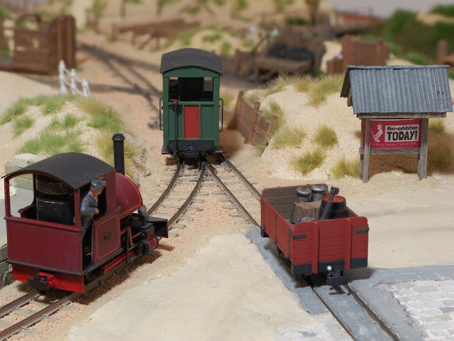
Above: A final shot of the brake van (facing the 'wrong' direction, and on a line it probably won't be seen on during exhibiting!). Also new in shot (aside from the open wagon) is that the little covered noticeboard actually has, after many years, its first noticeboard. During the 009 Society's 50th Anniverary Exhibition, I was talking to Sven (of Tramfabriek) about it, and he suggested that I use it to 'advertise' each exhibition that Sandy Shores attends. A novel idea, I felt!
I still of course have other things to update ahead of the MRC exhibition, but I've no idea if I'll have time to do them beforehand, as I have a photoshoot tomorrow, and again on Saturday... no rest for the wicked!


Comments
Post a Comment