As well as the small improvements made to Sandy Shores ahead of its outing to the MRC mini-exhibition as noted in my previous entry, there were a few new additions in the form of rolling stock - which I thought best to dedicate a whole post to. Sadly, the main one only arrived the day before, when I was at a last-minute photoshoot - so I did not have time to weather it (though it did see occasional use at the exhibition). It's a Minitrains N2SF:
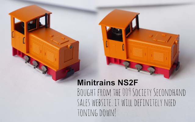
Above: Bought from the 009 Society Secondhand Sales portion of their website, I've had my eye on this Minitrains NS2F for quite a while! In the end, I actually found the blue version, which I thought would suit the layout better, on the website of a model shop (I won't mention which). However, a week after purchasing, having heard nothing, I was suddenly told the loco was not available. I found that very strange, particularly as shortly after, all trace of it was removed from their website - despite other liveries of the same loco present and still being labelled as 'Not in stock'! In the end, I obviously took a slight gamble on the £30 cheaper second-hand version from the 009 Society. The only reason (aside from not knowing exactly how it ran) that I didn't initially buy it first time around was that I didn't like the orange. But realistically, for £30 cheaper, it makes more sense to take the minor gamble and just repaint it into a less garish colour myself (if I can figure out how to remove the body!). Having tested it during the MRC show, it doesn't run quite as smoothly as my other Minitrains locos, but I think it just need a bit of running in, light oiling, and perhaps tweaking of any pickups. We'll see - loco maintenance/repair is not something I really do!
So, now that I have a working diesel loco, the railway obviously needs some way to 'refuel' it! There are two approaches I could take here; either make a diesel tank and sit it on a structure, or make a wagon-mounted tank. Except... I think I might do both, depending on how obtrusive the static structure would be on the layout! For the wagon-mounted tank, rather than have to buy yet another wagon chassis, I thought it made more sense to utilise one of the many existing flat wagons that Mark Greenwood designed and 3D printed for me. In a similar vein, After I searched online for some inspiration, I had a plan start to form in my head of what I felt would befit such a ramshackle railway...
Above: The tank itself is an easy build, especially when using magnetic squares like these ones from York Modelmaking. At this point, whilst I am trying to cut the sides and ends to the correct dimensions, I'd rather the top and bottom pieces were too big, than too small. As...
Above: ..it's very easy to remove any excess material. A bit of patience and a flat needle file is all that's needed for that, but the end result is worth it. Also, every edge and corner was chamfered using a light filing - just for aesthetic reasons. However, no sooner had I glued on the top piece, I realised that I really should've added some Deluxe Materials 'Liquid Gravity' inside to provide some weight for the very light flat wagons... oh well!
Above: To support the hose along the side of the tank, as per the model I was essentially copying, stanchions are created from wire. Sorry, but I don't know the gauge of wire, but it is the same used for the handrails of the stanchion kits from I believe either Wills or Ratio (I always get those two brands mixed up!).
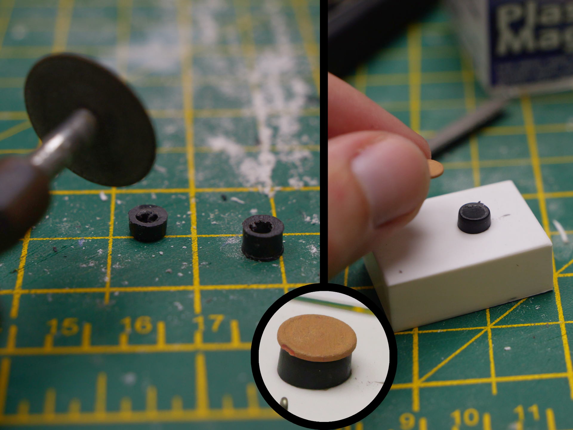
Above: To form the filler riser, what I believe was originally a circular bin from a kit (I think a HO scale kit of some description) was cut in half carefully using a Dremel with a cutting disc. Note that as it is hollow, the 'bin' was held with fine nosed pliers, being careful not to insert them too far and risk cutting them! In an ideal world, you'd cut something like this in a vice or mitre box, but I don't have those. To lessen the risk of disaster, I only cut part way through, and finished it off with a craft knife, with a flat needle file to square it off. Anyway, the filler cap is actually a circular wall tie from, I believe, the Wills Building Kit A?

Above: A tiny slither of styrene tube (sorry, I forgot what size) was sliced off a length of it, and glued to one end of the tank. As cutting such a tiny slither square is impossible, a flat needle file is used to square it off after the glue has cured. Next, a framework is built around the top of the tank. Two L-section girders are used upside-down on each end, which are then connected via 0.010" plasticard straps along the sides. Later, metal wire will be used in each corner to suggest the tie bars that in real life would anchor the whole lot to the bed of the flat wagon.

Above: The hose stanchions on the model that I was copying seemed to pass through the metal strap on one side that holds the L-shaped brackets in place on top of the tank. To make these holes, I used, I think for the first time, an archimedes drill. I bought it primarily because I couldn't get a collet small enough for my Dremel. Pleased to say it worked perfectly. Note the old I-girders used underneath so that I didn't have to drill into my cutting mat.
Above: As the holes in the metal straps were made central to reduce the chance of the thin plastic bending, it meant that weight needed to be applied to glue it in place against the tank to prevent the hose stanchions springing up - hence the resin barrels resting on top whilst the epoxy glue 'takes'! The styrene I-beam just visible below it makes sure all the metal stanchions are held under the weight of the barrels.

Above: Using a lit tealight candle to soften the hose to bend it to the required shape. This is a very difficult task, because not only do you have to be careful not to overheat and fully melt the plastic (which I did once), but you must also work quickly to bend it whilst it is soft enough. If that wasn't difficult enough, whilst forming one bend is easy, forming multiple bends is anything but! Every time I heated up the next curve, the first one would start to change/twist/straighten out... I got there in the end, though as you can imagine it was a tedious process. Oh, and note the inset photo, which shows the end, having been heated up, being pushed against the cutting mat in order to create a 'collar'. Or at least, make it look like it's a collar!

Above: Once the hose has been bent to the correct shape, it was then trimmed to length. The piece from the inset photo from the previous montage is seen here being glued to the end of the hose to form the 'tap' or 'nozzle'. The next photo shows a piece of, I think, 0.020" square section being glued to the collar to create a handle. You may note that the end of the hose that got cut off wasn't filed - the reason for this is not wanting to apply pressure and risk breaking the other glue joints etc. In the end, a tiny slither of plasticard was glued in place to hide the dodgy joint. The plastic cement softened the plastic a little anyway, so the end result isn't too bad, surprisingly.
Above: The final detail was to add a representation of a hinge for the filling cap. This was made simply by glueing on three bits of the same 0.02" square section styrene; two on the vertical riser, and one on the tank cap.
Above: As it was getting late on the eve of the MRC exhibition, I didn't take many more photos, so this is the only one I got painting it. The whole thing was basically given three quick coats of a generic grey, followed by the metal details all picked out in Vallejo 'Brown Sand'. Random patches of the tank itself then had the latter applied all over, followed by a few washes of it everywhere to tie everything together. It's a bit of a rush-job, but it's acceptable, I feel. The only thing I meant to do that I didn't was to paint the hose more of a dark grey than a light grey, for a bit of contrast.
Above: And here is the finished model in place, temporarily placed on a flat wagon as it will be on the layout. To be fair, I probably could (and should?) glue it in place - it's not as if I'm short on flat wagons!
Finally, (although made before the tank wagon load), let's talk about the other recent stock - this time, a Dundas Model L&B van, and the 009 Society 3-plank wagon (I've just received my renewal notice, so somehow it's already been 11 months since the kit arrived in the welcome pack - about time I built the 3-plank wagon then!). As the method of construction of both was practically identical, I'll just show the latter:
Above: Here's the 009 Society 3-plank wagon. Note that there are two sets of 2 identical sprues, so you do end up with an extra floor (which may be useful to fit a false floor, so that you can glue a wagon load to it).
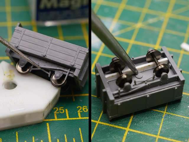
Above: The first step of any kit is of course to remove any flash and excess material. Some is easily removed with a flat needle file, but other bits are larger or more stubborn - hence the knife on the second shot!
Above: Using York Modelmaking's magnetic squares to aid assembly of the body sides. These little things are very useful, particularly as it means you don't need to hold things together whilst the glue sets. The holes in the centre of the magnets mean you can glue the entire joint without fear of glueing the magnets to the parts you are working on! Note that the second photo shows me lining the 3 sides up with the gridlines on my cutting mat to check the squareness - something I will also do once I've added the fourth side.

Above: The tricky bit is making sure that the solebars are sitting properly - both vertically and horizontally. I've learnt not to rely on the moulded pips underneath such kits as they are rarely perfect. As you may remember, my brake van suffers from wonky solebars due to this! What I actually decided to do, for better or worse, was to put the wheelset in at the same time as putting the second solebar on - hence why you see the end of the fine-nosed pliers pushing it in place whilst I glue it on. The final photo shows the brake rigging and pads glued to the back of the solebar.
Above: The final part of the kit is the brake lever, which just needs to be glued to the solebar on the side with the brake rigging. However, I wanted to add some weight to the bottom of this very light wagon, so two strips of 0.020" plasticard were glued underneath, which will later contain the weights. In hindsight, glueing them against the wheels (albeit with a tiny gap) wasn't the smartest idea as the wheelsets can no longer be removed!
Above: For weights, I use Deluxe Materials 'Liquid Gravity', though I've not found an easy way to glue the tiny balls in place yet! I used to use superglue until it started to cause the axles to tarnish, so I now use epoxy. It's neither easier adding the epoxy first, nor after the Liquid Gravity has been put into place. The former method means not all of it will be glued properly. The second method just means everything clumps together and you risk getting strings of epoxy everywhere when trying to level it all out again!
Above: The penultimate stage is to paint the wagon (the inset shows the L&B van). Note how I've painted the raised 'metal' straps first. I figured that otherwise it would make painting the sides of the minutely raised 'metalwork' impossible otherwise! Thoughts?
Above: Finally, we can fit the couplings. The first step is to use the Greenwich Coupling Height Gauge (the brass tool on the right photo) to mark the point of the wagon that sits 6mm above the railhead. Then, using a knife carefully, we can cut two vertical slits to mark the edges of the coupling, and then slice diagonally to take out two triangular chunks. To get it flat, rather than use a flat needle file (as mine wasn't small enough), I just carefully cut it away in several passes with the knife - checking constantly to ensure all was well. Then, it was a final check with the height gauge to check that I had the hole in the correct position.
Well that's it for this bumper wagon update. Next time, I'll discuss the static diesel tank construction. Not least because I haven't actually finished it yet!


Comments
Post a Comment