Sandy Shores - Fiddle yard rebuild and water tower detailing

This post had been partially written months ago, just after Sandy Shores visited the 009 Society's 50th Anniversary Exhibition at Statfold Barn - apologies for the delay, and that things are out-of-date!

All of a sudden, the forthcoming 50th anniverary celebration exhibition of the 009 Society was bearing down on me! I feel very privileged that Sandy Shores was invited all the way to Statfold Barn in Tamworth for this exhibition - all despite me not being part of the 009 Society at the time (duly rectified in time for the show!). It was thus time to set the layout up in the studio and see what needed fixing, modifying, or maybe even rebuilding...

Fiddle yard

An important aspect of the layout that has never worked 100% is the fiddle yard. I did improve reliability somewhat by rebuilding the sprung contact wipers before the previous show in Basingstoke, however, it was still not perfect. In addition, there are other issues that I had with it:
  1. Not all the rails seemed to line up perfectly - it seems like the approach track had twisted/raised slightly (or was never perfectly installed in the first place).
  2. There had never been a need to turn the turnplate more than a few degrees - since;
    • the locos derail if going bunker first towards the fiddle yard from the loco shed headshunt (so I don't ever turn them)
    • there is no run-around loop, so there's also no need to turn entire trains
    • the three sidings shown in the photo of the fiddle yard below never get used despite being wired up - not even to hold stock on!
  3. There is very limited clearance between the three tracks on the turnplate.
  4. There is limited siding capacity.


Above: An overview of the fiddle yard, with the turnplate surface removed. Note that it only rests on the 4 white rubber pads just visible on the lazy susan - it is not secured permanently!

Above: A montage showing the tight clearance on the current turnplate, followed underneath by a potential traverser with a wider track spacing. Note: whilst I've shown a 5 track traverser, in reality, a 4 track traverser would fit the space better - otherwise the control panel would not fit without overhanging the baseboard edge.

And so off I went to knock up the design on my computer using Sketchup. After a bit of trial and error, and numerous versions, I settled on this:


A 3D model of the new traverser fiddle yard. The approach track is lined up with the 1st track.


Above and below: The new traverser will be about as simple as it gets, and will use a combination of techniques used on the original turnplate, together with a redesign to make things more serviceable. By which I mean the four tracks of the traverser will still be powered straight from the approach track, but via sprung 'wipers' that are on the surface of the baseboard rather than hidden underneath. That means both installation and maintenance should be MUCH easier! In addition, the traverser will lock into place using a simple brass barrel bolt - which will slide into metal brackets to provide a simple, yet secure means of indexing the traverser that shouldn't wear much over time. You may remember that the old turnplate was alignment-by-eye only, and caused no end of derailments as a result!

A 3D model of the new traverser fiddle yard. The approach track is lined up with the 4th, and final track.

In the 3D render below, I've superimposed the old turnplate fiddle yard with the new traverser. The latter is only about 43mm longer than the original (as it turns out, it's about half of that shown in the 3D model), so will not result in an increased space required to operate the layout (as I always added an extra two feet on exhibition manager handouts in case access was required past the end of the layout).


A plan view of the 3D model of the new fiddle yard - with the older fiddle yard shown superimposed to compare sizes.

Above: Superimposing the old with the new fiddle yard shows only a marginal increase in board length, but with greater storage capacity. Another handy design feature is that the traverser tracks are exactly the same length as the headshunt on the layout - so I will never have to guess the capacity of both ever again!

A further happy bonus of this new fiddle yard will be a longer approach track, which should mean that I will be able to add, if desired, even more 'fake scenery' onto the fiddle yard to further disguise the transition between scenic, and non-scenic areas of the layout. It should also stop hands being so visible beyond the scenic section!

A montage showing how the sprung wiper system works to maintain electrical connectivity.

Above: A close-up of the sprung wipers and copper-clad board electrical contacts. A simple, but effective method of carrying electricity from the approach track and onto the fiddle yard. Having it above-board means maintenance is a doddle.

Dismantling the old fiddle yard.

Above: The destruction of the old fiddle yard commences. Rather alarmingly, some of the softwood blocks visible were never actually secured; no glue or screws whatsoever! Thankfully these were not the important ones. In any case, the disassembly was very straightforward as only screws has been used to construct the fiddle yard originally (well, the bits where I remembered to fasten them down!).

Testing the proof of concept.

Above: With a blank canvas, I could offer up the drawer runners to determine the spacing of the tracks. Note that I've drawn the location of the battens that will make up the edge of the traverser 'well', as well as the new location of the LED driver that powers the LED lighting.

Creating a softwood framework on which to build the traverser.

Above: To support the far end of the traverser, a new softwood frame is built. The circular piece of 5mm plywood underneath supported part of the turntable, but never had framing underneath it; there wasn't much weight on top, and there were also wooden dowels and a further 5mm plywood top to provide the necessary support instead. Anyway, the softwood frame shown will be screwed to the underside, and will later have a thick ply end piece (nearest the camera) to support one of the drawer runners. The rightmost photo shows the rubber stoppers that are to be removed. These provide a positive 'lock' when the drawer runner retracts fully. This is not good for model railway traversers as it will create resistance that will have to be overcome to start moving the traverser. Resistance that could cause stock to topple over quite easily.

Building up the surrounding walls of the traverser 'well'.

Above: Perhaps stupidly, rather than cut off the old circular bit of 5mm plywood that once supported the turntable, I opted to leave it in place. I really should've replaced it with a bit of ply to cover the remaining holes in the new framework! In any case, the left photo shows the thick bit of 12mm plywood on the end mentioned earlier. Additionally, some 3mm hardboard creates the fascia for the back part. The rightmost photo shows the new framework on top of the fiddle yard - which is built up with 45 x 45mm softwood and 18 x 45mm softwood. Note also additional 3mm hardboard fascias for the inside of the 'well'.

Adding the drawer runners to create the traverser.

Above: Fixing the runners in place is a critical aspect. The drawer runners should be absolutely parallel, and they must also match the same angle as the approach track baseboard (which is hopefully level!). The height also needs to be thought about carefully. I chose to fix the inside battens onto the drawer runners (that will later support the plywood traverser top) first. These blocks are positioned about 1mm above the height of the runners so that there is no friction between the plywood top and the runner - the plywood top will overlap the runner, though I suppose you could instead overlap the 'approach' woodwork instead. Nethertheless, once these blocks are perfectly aligned with the runners, the assembly can be screwed into the 'well'. The arrow in the top photo shows the lever which will allow you to pull out the internal runner for you to access other screw slots. Speaking of which, the slots allow you some 'play' - you can screw, check, slightly unscrew, adjust, and refasten until you get everything perfect. You will want to temporarily place the plywood top on in order to test this. The more time and effort you spend testing and making adjustments here, the less problems you'll have later, and the better the reliability of the traverser.

Adding the traverser platform.

Above: Happy that the test fit of the plywood top shows all is well, and that nothing is binding, it can be screwed on. The drawer runners are in three sections, which means they can extend to twice their original length; in actual fact, I didn't quite need the full extension here. Another useful feature of these particular runners is that the ball bearings make for very smooth action, whilst also reducing the amount of 'play' in them.

Using the removed fiddle yard as a template to make a new approach board.

Above: One thing I should've taken a bit more care of is the approach board. I used the original as a template, but as can be seen, the angle was not quite right where it meets the traverser. This isn't too problematic as we only have one approach track; so long as we ensure the plywood top doesn't impede the movement of the traverser.

Adding fascias to the traverser table to hide the innards.

Above: Happy that everything works nicely, the fascias can now be fitted to the sides of the traverser. Note the bits of white plastic (cable tie bases) temporarily holding this piece above the bottom of the 'well' whilst I screw it into place - this will create a gap to prevent the fascia potentially scraping the well.

Copperclad board cut into small lengths, and 'gapped'.

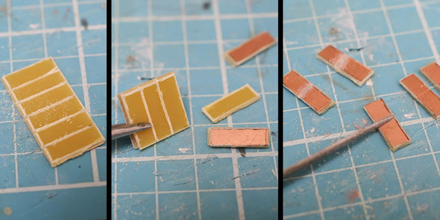
Above: Now that the woodwork is pretty much done, we can turn our attention to the mechnical operation and wiring. First up, we'll need to cut a bunch of copper clad boards so that we can later solder wires to them. These ones will be located on brackets beside each track. Note that they are scored both front and back, and then snapped off using a pair of fine nosed pliers. Then, each panel will need to be gapped by filing a centre line into the copper; removing it, and showing the fibreglass underneath.

Cutting aluminium L angle with a circular saw, then marking holes for a barrel bolt to pass through them.

Above: Two types of brackets will be needed: thin ones beside each track, and wider ones that will have a hole cut in each. The latter is required for the barrel bolt, which will help create the traverser indexing, to slide in. To mark the correct height of the hole, the end of the barrel bolt is coated in felt tip pen. The bolt is then slid across until it touches the bracket - thus marking the centre point of the required hole.

Above: The aluminium angle will obviously need holes drilled for the barrel bolt (that's another story entirely as it took ages to find the perfect sized drill bit!), but to make sure there is minimal propensity for the brackets to move and thus ruin the traverser indexing, I decided to screw them down. This of course means that holes are also needed to be drilled for that. Two screws of course minimising the tendency for the brackets to twist. To drill the holes successfully, two things are key; firstly, using a punch and hammer to dent the aluminium to guide the drill bit, and secondly, to use a pillar drill (thus ensuring the hole is perfectly vertical. Note that a vice is used for safety reasons, and also as a further way to make sure that the drill bit doesn't wander.

A replacement top surface for the fiddle yard was cut from a single piece of 5mm ply. The whole fiddle yard is then painted dark grey.

Above: Before the new plywood top for the non-traverser section of the fiddleyard is secured, the approach track position is marked on top, two small holes are drilled either side, and a black and a red wire is fed through; which will later power the entire fiddle yard. Something to note is that the screws that secure the plywood top to the softwood supports underneath had their holes countersunk to ensure the screw heads sit flush, or below the top surface. The whole fiddle yard was then painted with the same dark grey paint that the fascias and layout trolley were when first built. Note the messy wiring of the control panel - something to fix another day!

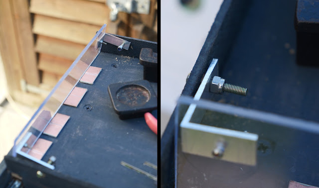
A perspex length is hinged to the inside of the walls of the traverser, which drops down to prevent stock rolling off.

Above: Whilst I was continuing to cut and gap copper clad panels, my Dad was tasked with making a way to prevent stock rolling off. It wasn't long before he came back with a length of perspect bolted to two aluminium angles, which he then bolted to the inside of the walls of the traverser. This meant it could be dropped down to cover the ends of the traverser tracks.

Glueing copper clad panels to aluminium angles.

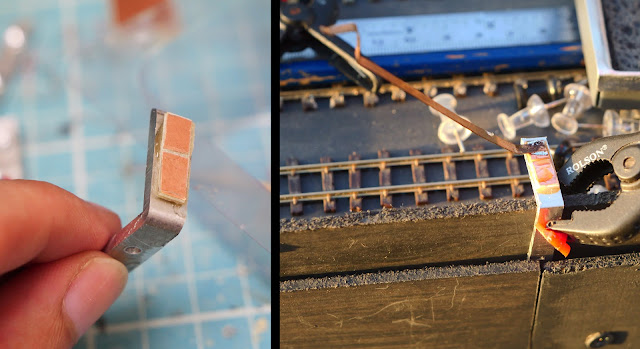
Above: For the narrower aluminium angles, these have a copper clad panel epoxied on one of the 'front' sides, making sure to keep them at roughly equal height. One of them will then have two sprung contact wipers soldered; one on each part of the gapped copper clad panel. Note how the end of the sprung wipers are bent to form a V shape, to minimise the chance of them snagging against the other aluminium angles on the traverser.


Soldering railway track to copper clad panels, and then adding narrow aluminium angle lengths between each track to help pick up the electrical current.

Above: Now that all the copper clad panels have been cut, gapped, and epoxied into their correct positions, the track can be soldered to them. As the approach track had to be relayed now that it needed to be longer, a single piece of track was used for this, and the first traverser track. This meant that I could be 100% sure that at least one track would align perfectly! These rails, once fully soldered, could then be cut with a cutting disc on a Dremel. The rest of the tracks were mainly aligned by eye, though I did put a straight edge to each side of the rails to check the alignment was correct. Something to note is that the barrel bolt on the traverser was engaged with the relevant aluminium bracket whilst soldering the track in place - the brackets had previously been secured to the non-moving part of the fiddle yard at regular intervals, at the same time as the copper clad panels were glued.

The narrow aluminium angles (which the sprung wipers will strike against for electrical power) were then screwed to the traverser; making sure to keep them all at the same distance from the adjacent rail to the left. That meant everything aligned as it should, and that the wipers will always contact the correct angle to provide power to the relevant track.

Sprung wipers soldered to the copper clad panel on the alumunium angle attach to the fiddle yard.

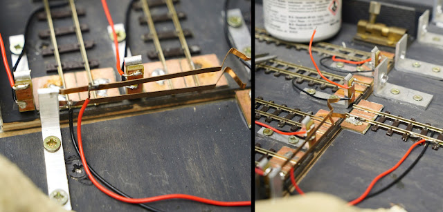
Above: The power onto the sprung wipers is taken directly from the track (though I suppose I should've just taken a feed from the control panel!). The righthand photo is a reverse view looking towards the traverser, showing the wires from the approach track soldered to the sprung wipers. This view also shows the wires soldered to the copper clad panel of one of the traverser tracks in more detail. The sprung wiper will make contact against this when its track is aligned with the approach track, thus giving it power to both rails - simple!

Wires soldered to every copper clad panel, and then to each track.

Above: A couple alternate views looking from the layout towards the traverser. It's not the neatest job, but to be fair, I was in a rush! You'll have to excuse my soldering - the irons' tip is not in good condition, to put it mildly.

A final overview of the new fiddle yard, showing the 4 fiddle yard traverser tracks, the approach track, and the aluminium angles, wiring, and barrel bolt.

Above: A final view of the wiring set and general fiddle yard set up. The inset photo shows my mistake not double-checking which way around the wires should be; thus I had to reverse the wires after everything shorted upon powering the layout! At least it wasn't soldered, just screwed into the connector. Ignore the screw poking through...!

An overview of the completed rebuilt fiddle yard in use.

Above: A final overview of the rebuilt fiddle yard. Note the wooden knob that provides a safe way to pull and push on the traverser. Someone asked me why it was there, when the 'handle' of the barrel bolt could be used instead, resulting in only one hand needing to be used to lock it in place. The answer is that, for some reason, the traverser sticks if pushed from that end! This photo also shows why the perspex drop-down shield is necessary.


Minor additions and repairs

As seemingly happens after every exhibition, the headshunt trestle is the first item on the agenda in terms of needing repair. Noted previously, the handrails are incredibly delicate, and it only takes one second of lapsed concentration when maneouvring the layout to get it snagged on something and demolish the handrails and even the buffer stop. Fortunately, I kept the broken section of handrail safe in the box where the buildings are placed for transportation - so it was a simple case of gluing it back on with a steady hand.

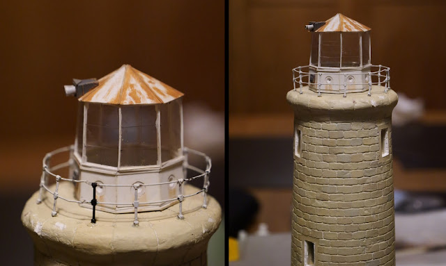
Elsewhere, the lighthouse railings are another delicate feature. Unfortunately, these often take a battering, too! Mostly because I have no way of transporting it safely, so it often sits on the front seat of the car on the way to/from exhibitions! I was doing well keeping it safe on its last outing until I got home - upon releasing the handbrake to reverse the car into my drive, I wasn't looking where I was putting my hand, and clipped the lighthouse railing; instantly breaking it into 3 sections... whoops! A bit of bending of the wire with some fine nosed pliers and some epoxy later, and, whilst not perfect, it is at least more-or-less back in place... until the next time it isn't!

(Post-show report: Coming back to finish this blog entry after the show, I can attest that it certainly wasn't long before it got damaged again - my Dad dropped the lighthouse because we had wedged it against a bunch of coats and a closed car door in order to 'keep it safe'! Needless to say, he forgot the warning about 'NEVER open this door' when it came to unloading the car at the holiday cottage. He was mortified, but the damage wasn't too bad surprisingly, and I could fix it the night before the show. To be fair, what a stupid place to put the most delicate object!)

A two photo montage showing the lighthouse railing being repainted.

Above: I didn't take any photos of the repair post-Basingstoke, however, I did take a couple of the similar repairs made whilst staying at the holiday cottage! Note also that I added some rust marks to the lantern room, and that there is definitely a little bit of damage to the stonework at the top of the tower itself. These photos don't show the damage of the railing itself, but it 'only' fell apart into 3 sections, with one post being damaged, and a few of the wires bent in the wrong direction. As can be seen, it's not a perfect fix, but it'll do until I can replace the railings completely.

Elsewhere, it occurred to me that it would be a good idea to glue some things together that were previously just loosely 'assembled' whenever the layout was set up - such as the roof of the lighthouse lantern room, and the ladder to the water tower. This also gave me a great excuse to further embellish and detail both of these. Let's start with the water tower:

A montage showing a loose ladder being fixed to a scale water tower using glue and wooden supports.

Above
: Until now, the ladder for the water tower was precariously left leaning against it, and often toppled over if the layout was shaken. The rightmost photo shows me gluing the ladder in place, using thin wooden strips to also secure the bottom of the ladder. Note the picnic bench and 009 sleepers used to get the height required to simulate the coaling platform!

A flame from a candle is used to soften a piece of round styrene in order to bend it to form pipework.

Above: The water tower has never had any detailing fitted, note even a pipe and hose. I decided to form both of these using one piece of styrene. By softening styrene rod over a flame for a couple of seconds, it could be bent around a cylindrical object to get the 90 degree angle required. A representation of the connection to the tank is simply made by heating the end and pressing it against a metal rule. The rightmost photo shows the 'hose' - made by heating it again, and pressing/twisting the soft plastic with a pair of fine-nosed pliers/grips; the teeth of which helped add texture. To represent the transition between pipe and hose, more heat was applied, and the two sections were squashed slightly together to form a bump. The hose side was then filed slightly to form a narrower section.

A representation of a pulling 'cistern' mechanism is made using multiple layers of plasticard.

Above
: By studying various prototypes, I opted to represent what I would describe as a Victorian toilet 'cistern' mechanism! This was simply made using multiple layers of plasticard, and some incredibly fine plastic rod (the light brown bit on the rightmost photo) to act as a rope. The darker brown 'knob' (supposed to represent a counterweight) is just an offcut from a random sprue. Note how the 'rope' is bent at the end, and pushed into a slit in the arm.

By this point, it was time to pack everything up and head to the holiday cottage (so photos from now on won't be as good quality as the lighting was less-than-ideal there)...

A three photo montage showing the addition and painting of the various pipework detail onto the water tower.

Above: Having brought all my paints, glues, paper towel, and even a small jamjar of water so that I could use its lid as a paint palette, I got to work finishing off the water tower by adding and painting the new detailing. As well as the outlet pipe/hose and the 'cistern' mechanism, I also added a thin inlet pipe so that it looked as though there was a feasible way that water could enter the tank. Oh, and I just realised that I never showed the tiny handrail I added from finely chopped lollipop stick. You can just about see it on the top of the 'landing' above the ladder if you look hard enough!


Well, that's everything for this blog entry. Coming up next time, we'll discuss another fairly big change to the layout...

Comments