Converting half a garage into a studio!
After 7+ years of working in my crampt bedroom (with room only to walk in and sit down), I finally get some space to build a studio...
It's been a long dream of mine to have a purpose-built studio space. In fact, for the past 7 years, I've designed probably between 10 and 20 standalone studio spaces; having planned to build one in my parents' garden. Since then, our entire garden has been renovated drastically, and there is no longer room for a studio. However, since my dad was vacating half of the garage (the other is for storage), I seized the opportunity, and was granted the go-ahead to build a space that would allow my desks and modelmaking stuff out of my tiny childhood bedroom. Needless to say, I'm incredibly grateful to my parents on all accounts.
Happily, my dad was a carpenter; he has therefore shared expert knowledge, and has done all of the technical bits. I've tried to learn what I can from him, but there are certainly things I leave for him to do; like hanging the door, and cutting wood straight!
I'll be updating this post whenever progress is made, so check back soon!
CONTENTS:
(Click on a day description to jump to it; there is also a link to jump back to this spot at the bottom of every day!)
Days 1-3 (9th-11th Oct): Clearing out old benchwork |
Day 4 (12th Oct: Moving the old partition |
Day 5 (13th Oct): Store tip no.1, finishing partition |
Day 6 (14th Oct): Door, rear wall framing and insulation |
Day 7 (15th Oct): Flooring (joists) |
Day 8 (16th Oct): Window wall framing, flooring cont. |
Day 9 (17th Oct): More flooring, a ply wall cover, & the final wall started |
Day 10 (18th Oct): Last wall framing, door lock installed, & flooring complete! |
Day 11 (14th Nov): Boxing in the brick pillars |
Day 12 (15th Nov): Penultimate walling, plus first signs of paint! |
Days 13-14 (18th/19th Nov): Lights, painting... skirting?! |
Days 15-17 (20th - 22nd Nov): First storage unit - Pt.1 - Carcass |
Day 18 (27th Nov): First storage unit - Pt.2 - Drawers |
Day 19 (23rd Feb): General Update (window, lighting, electrics) |
Days 20-21 (27th/28th Feb): Electrics and ceiling |
Day 22 (6th Mar): Final electrics, skirting and ethernet |
Days 23-26 (16th-19th Mar): Pegboards |
Day 27 (20th Mar): Window |
Days 28-29 (21st/22nd Mar): Trim (Pt.1) & floor varnishing |
Days 30-32 (23rd, 26th & 27th Mar): Trim (Pt.2), monitor shelf, roller blind, & acoustic panels (Pt.1) |
Days 33-34 (30th & 31st Mar): Painting the skirting and the music desk |
Day 12 (15th Nov): Penultimate walling, plus first signs of paint! |
Days 13-14 (18th/19th Nov): Lights, painting... skirting?! |
Days 15-17 (20th - 22nd Nov): First storage unit - Pt.1 - Carcass |
Coming soon:
- Acoustic panels (Pt.2)
- Wall sign
The Design
It probably goes without saying that the design has gone through a number of changes. Even this one is outdated, but not by enough to warrant a redraw. The premise is simple, the original partition is moved down by about 500mm to give a nook for my large music desk. A kickback wall allows direct access to the unconverted section of the garage through the side door without having to go through my new studio. The new partition door (at 45 degrees) will no longer open into the studio, as we decided to reuse the existing very tall (2200mm) door. As the floor will be raised in the studio, it would obviously no longer be able to open as drawn. Still, more space for me!
The studio consists of a small storage wall on the left end for Sandy Shores, modelmaking stuff, and possibly a new layout?! The right hand wall is a storage wall for everything else, including a nook for my folding modelmaking desk. A homemade photography table will also need to be built (bringing my desk count up to 3!). Note the new stud walls against the single skin walls. Annoyingly, there are weird brick piers, so we cannot insulate these without considerable loss of space. The old window (made by my dad 30 years ago) is in dire need of replacement (not bad for 30 years!).
All in all, it may not be the standalone purpose-built structure that I dreamed of, but it'll be a hell of a lot cheaper and more convenient!


Construction Diary
Days One, Two, & Three: Removal of old benchwork
Dad was alone for the first few days dissassembling his old benchwork around the walls and moving stuff, whilst I worked on a modelmaking commission...

Above: Three days into the build, and most of the benchwork and stuff in this half of the garage has been removed. The stuff against the window is still there now (6 days in), but it needs sorting out and space found for it before we can move it; so for now we're working around it. The rack hanging from the ceiling (above the window) was where one board from Calshot MkII had been stored for 8 years, until I demolished it recently! Note the original partition and doorway on the right hand side. This will be moved further to the right, the door relocated immediately in front of the camera, and a new internal partition built (see the plan above).
Click to go back to the top of the page
Day Four: Moving the old partition wall

Above: First things first, we needed to move the far ceiling/suspended rack and its contents so that we could move the original partition. Once that was done, the ply was taken off of the original partition, and the right hand side partially tacked onto the leftmost one, and moved to its new location. The rest of the right side was carefully taken apart to scrounge some studwork to complete this new partition. Basically, turning the left photo into the right photo! It's hard to see from this photo, but we've tacked on some DPC (damp proof course) to all studs that sit against the single skin brick wall.

Above left: That took a fair while, so by the end of the day we just had enough time to roughly mark out where the rest of the new partition will sit. This has altered slightly from the original plan, with a greater depth for the desk area, and a larger storage area where Sandy Shores will be located.
Above right: I purposefully kept the wall angle here at 45 degree to make our lives easier; as you can see, the circular saw has a tilting base, so the angles for the ply wall coverings were also a breeze to do!
Day Five: Store Trip No.1 + Partition "Finished"

Above: Donning our lovely homemade masks (and fogging up my glasses in the process), we headed over to Wickes to get the first batch of materials required. Some of which can be seen here. There were 24x 4'x2's (seen above), 2x 100mm fibreglass batts, screws, rawlplugs, and finally some smaller 3'x2's to match the existing partition studwork.

Above: Back at home, and good progress is made with the aforementioned 3'x2's; the remainder of the new partition is built, with 12mm ply added on the other (unconverted) side. Apologies for the mess; like I said, with limited space available currently, it's been a case of moving everything around on an almost constant basis. Anyway, just like that, the day was over!
Day Six: The door, and rear wall framing
Above: The first job today (14th Oct) was for dad to show his magic at door hanging. I left him well alone for this bit; he used to fit doors (as well as other carpentry aspects) at a portable building firm. It's really mesmerising watching him work; he chiseled each hinge rebate out in 59 seconds or less. It would take me 10 times longer than that, and it still wouldn't be as neat, I can guarantee! Anyway, with the hinges put in place, the bottom and sides were planed off; a process that takes time, muscles (due to the large amount of times the door has to be maneouvred in/out to check the fit), and persistence...

Above: But it wasn't long before it was in place. The lock and handles are on the next shopping list. Note how the door misses the filing cabinet in the hallway by mere millimetres; now that was good planning (if I do say so myself!).

Above: The rest of today was spent framing up the rear wall. Here's how it looked after the socket had been moved over to the new partition. Note the two awkward brick piers on either end!

Above: A few hours later and we have the stud wall up. As you can see this is not just a simple case of putting up a simple frame. Well it is, but I specified that we should add some prevantative measures due to the nature of being in a cold, single skin brick garage. First, breather membrane was nailed to the top cill (the one above the brick wall that the rafters sit on top of), and unrolled downwards. The lengths were taped together, and also covered the brick piers (these have not been secured on here as we have not yet put any wooden framework above them). Additionally, all the framework had DPC against the wall/concrete side. Better safe than sorry!

Above: And finally, we could use most of the two "loft insulation" batt rolls to provide 100mm of lovely itchy fibreglass insulation. (Actually, it was nowhere near as bad as the old style of fibreglass!) That went up incredibly quickly. It's nice not to have to work with Celotex, let me tell you!
Tomorrow will be another trip to Wickes for the flooring (more 4'x'2s and floorboards), plywood (for the walls), the door lock & handles, more insulation, and probably a whole heap more. This studio won't be big nor cheap, but it's worth doing properly regardless; I've waited long enough for a home office/workshop/studio!
Day Seven: Store trip no.2 & half of the floor joists
Another day, and yet more progress; first on the cards was another trip to Wickes for a considerable quantity of timber. An additional 20 2'x4's, 5 of the 6 packs of floorboards required (they ran out, rather annoyingly!), two new saws, a set of door handles and the lock for them, and another roll of insulation. Oh, and 4 out of the 7 required 18mm plywood sheets for the walls. Phew. Another £380 out of the bank, and a fair amount of weight in the van for the trip home!

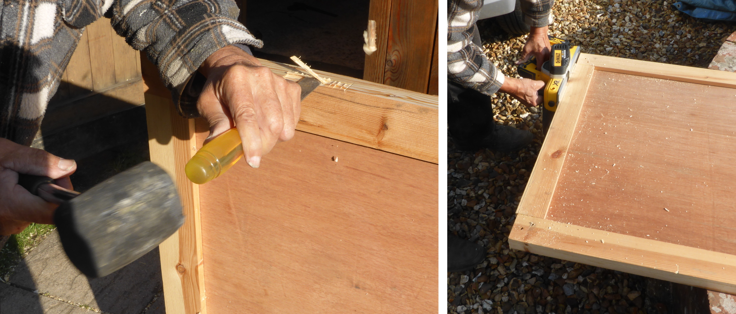
Above: With the partition and rear wall studwork all finished, it was time to start work on the floor. The most important thing about flooring is to make sure it's all level. This floor is most certainly not! I'll get onto that later, but first my Dad had to notch around the first brick pier in the corner. To do this, he chose the laborious method of cutting slits every centimetre to weaken the wood. After 39 scraps of wood (yes, I counted them!), the notch was cut.

Above: As I was saying, getting the floor level was incredibly important, and we started from a single datum point on the corner of the new kickback partition wall, then worked our way back to the rear wall, across the rear wall, and back to the far side again. As you can see, on the far left end of the rear wall (window end), the difference is quite staggering!

Above: This photo shows two things; firstly, that there are loads of blocks screwed to the frame and resting on the concrete floor to help keep the new subfloor level. Secondly, it shows that the joist in front of the door had to be notched around the door lining. Three saw lines and a mallet and chisel made short work of that!

Above: With the first section of joists in place (again, note the blocks holding the frame level), we could lay some insulation in the gaps, and temporarily place a sheet of 18mm ply to store some of the tools and junk in this room to give us more space to move around. Note that we didn't feel the need to add any sort of breather membrane. The stuff around the bottom of the wall plates and the membrane therein should be plenty to keep moisture at bay!
div>Tomorrow, with any luck the floor joists will all be in, and maybe we can even make a start on the flooring itself!
Day Eight: Window wall framing & flooring cont.
A pretty big update for today!
Before we could finish the floor joists in this half of the studio, the interior stud wall on the window wall (well, the top, bottom, and a few vertical studs) had to go in first so that we knew where the floor needed to go. This method of construction means that only the new partition wall needs to be screwed into the concrete floor; the rest of the studwork walls will be sandwiched and held in place by the floor joists! It saves a lot of hard drilling into concrete...
Before we could finish the floor joists in this half of the studio, the interior stud wall on the window wall (well, the top, bottom, and a few vertical studs) had to go in first so that we knew where the floor needed to go. This method of construction means that only the new partition wall needs to be screwed into the concrete floor; the rest of the studwork walls will be sandwiched and held in place by the floor joists! It saves a lot of hard drilling into concrete...

Above: This photo was taken after the first few studs on the window wall have been put in place, and as we can see, the rest of the floor joists in this area are now in place. For the brick pier/pillar in the far corner, we chose a labour-saving method (compared to yesterday) of simply adding a secondary short joist in front! Note the breather membrane already in place, and the DPC once again nailed to the back of the studwork. On the floor joists, the small blocks of wood every foot or so show that the original concrete floor is far from level...

Above: Now that the floor joists were in (there is still more to do, but we can't do it just yet as we have one more wall to go in), the rest of the framing on the window wall could go in. Extra studwork is required in window openings to support the top and bottom rails. (Sorry about all the cobwebs!). Oh, and the close-up shows the notch cut into the rear of these 6 studs to allow room for the lintel behind.

Above: And here's the finished framing on this wall and floor; all complete with insulation of course. As a bonus, we now have a window sill big enough to put boxes of screws on; it's the small things in life!

Above: Even though we haven't done all the floor joists, we ploughed ahead with laying the floorboards we bought yesterday. These boards were the cheapest we could get. I know last time I said I want to do everything properly, but I don't want anything nice for flooring because it's very much a working room; we have expensive hardwood flooring in the kitchen, yet it is very scratched in places. Seems silly to me to pour money into expensive stuff that you tread on! I'll be painting them anyway, and plan to use a plastic mat around my desk area.

Above: Anyway, here's a neat little trick for laying tongue and groove floorboards that my dad taught me! If your boards aren't quite pulling together, use a scrap bit of floorboard to protect the tongue, whack a chisel in the joist, and use leverage to hold it tight whilst you (or someone else) bangs in a nail. Simple! Oh, and don't forget that you won't want to nail this front side down until you've placed the next board; or you'll never get it in...

Above: This isn't quite all the flooring we got done today, but it does show that we've made great progress. We've done about 60% of the flooring in total. Looks like another trip to Wickes tomorrow for more materials!

Above: Thanks to the hefty amount of progress made, we were even able to put the first sheet of 18mm plywood on the rear wall. I've included a close-up to show the bizarre star shaped screws! They do look kinda cool, even if it took us a while to find a drill bit to fit...
And there we go; that's everything from today. Tomorrow, a third trip to Wickes is on the cards. My poor, poor bank account!
Day Nine: More flooring, a plywood wall, and the final stud wall
Today started off slowly, securing one sheet of plywood to the partition. Another trip to Wickes was then needed to pick up some flooring, more breather membrane, and half a dozen studs (amongst other things). We eventually resumed work at 3pm; just a few hours from sunset! Despite that, we got a reasonable amount done! Let's take a look...

Above left: With extra floorboards picked up (another 4x packs of 5 boards), we carried on laying what boards we could. As my dad pointed out, most people don't bother pre-drilling the holes when nailing them down, but do that and you risk splitting the wood.
Above right: Another aspect I was taught was a trick on how to lay boards in tight or awkward locations. This image shows exactly that; a wedge shaped end board, with a notch cut out for the door lining. Tongue and groove boards would normally make it impossible to lay like this as you cannot just place it in; but rip off a short length of the bottom bit that forms the groove, and you can just place it on top as if it was a normal board. Simple, but effective.

Above: This photo was actually taken after we finished for the day, but I've included it to show how far we got with the flooring; almost done! Anyway, back to the correct timeline now...

Above: As mentioned in today's description, we also got another wall covered with plywood. Part of this meant a hole had to be cut for a double socket (for its lining box that is). The easiest way to do that is with four corner holes cut from a large bore drill bit, followed by cutting the rest out with a jigsaw. A very fast and efficient method which takes no effort at all (although those drill bits can be a bit tough to control).

Above: With the socket hole cut, we could feed through the existing wires and socket (which will be replaced later with a more modern flush fit box). This socket and cabling actually ran to the middle of the left wall. In order to move it to its new location, I ventured into the loft, removed one of the (thankfully not nailed down) loft boards and pulled the socket up over the rafters. This allowed it to be re-routed along the top of the new partition, with notches cut for the wires through the various studs...

Above: ...which brings me onto a very important safety point! It's always worth marking where your live wires are going. When we first moved the socket, I wrote notes on the rafters above with measurements telling us where the new wiring was. Now that the ply is up, this had to be translated on to the boards with a hatched marking. I told Dad it might be worth writing "DANGER!" as well... but for some reason he scrawled "LIVE WIRE" on top of the hatching, making it barely legible. I found it hilarious, but it really is important to be safe when you're around live wires, obviously!

Above: As mentioned earlier, we only had a couple hours or so to work on the room today, but we did manage to get the top and bottom sills onto the final wall. Before this though, we had to add all those wooden blocks on top of the three brick piers/pillars in the room. For those that were close to the ceiling joists (like this one), wedges were used to help hold the block in place whilst we screwed it on.
Also of note is the new type of breather membrane on show. We ran out for this corner originally (see the leftmost photo), hence why we could not complete the window wall and the flooring yesterday. Annoyingly we had to buy a 20m roll even though we only needed about 2.5m. An expensive annoyance!
Anyway, look to the far right image and you might just notice an additional two blocks at the top. I should've arrowed them, but they are top left and right of the photo. These will later be needed to secure the 12mm plywood sheets (that will act as the ceiling), as there are no ceiling joists there. However, the ceiling will only be done once the electrician has done his or her magic (and I haven't even got the downlighters yet; so it will be a fair while!).
So there we have it, a bit of a wordy update, but hopefully it has been informative! Tomorrow is a Sunday, so really I shouldn't be working on it, but I doubt I'll be able to stop myself. That said, I have a deadline approaching very quickly for a commission, so I might have to restrain myself... we'll see!
Day Ten: Last wall fully framed, door lock installed, & flooring complete!
So much for restraint; by the time I got downstairs at 9.30am to admire what we have already completed in a week, Dad was already putting in the last remaining vertical studs! Cue me quickly making a pot of tea and donning a coat to help out in the cold...

Above: By the time I got to the garage, this is what greeted me; the four vertical studs are now in, complete of course with DPC behind. The bottom floor joist is only resting on the floor temporarily for now...

Above: ... and it was my job to make sure it was placed level, or at least as level as possible! This is tough because this is the last piece to go on, and must be level in three directions. After a bit of packing up, I eventually got it pretty close. It's not perfect, but as this will be a storage nook anyway, I'm not going to spend too much time faffing about. The short joist I put on the right to cover the pillar did need a bit of fettling, but I got there eventually.

Above: With the tough bit done, I could go ahead and screw in the noggins and floor joist supporting blocks whilst my dad cut them to size outside. In some places (due to lack of access), one screw placed into the side rather than two in the end will be all that is required. N.B. The walls aren't bent in the left photo; it's just the effect of the panoramic format!

Above: As mentioned, the supporting blocks for the floor joists also went in; we only just had enough screws for this! Anyway, as always the voids are filled with 100mm of fibreglass insulation.

Above: All this meant of course that the flooring could now be finished! Here, my dad is using a sliding bevel to accurately mark the boards by the door. This same angle on the sliding bevel is used for all of the boards along here; so there's less time spent marking out by not having to measure it every time!


Above: I thought that after yesterday I'd get a clearer photo of the method for getting tongue and groove boards into tight locations. The arrow points to the thin bottom lip that you can remove on the last 300mm or so to help get these boards in. Try not to remove more than necessary though, it is there for a reason, after all!

Above: The momentous (to me, at least!) occasion of the last board going in! Note the nail yet to be hammered in on the edge of the preceding board; we don't want that board to be so tight that we can't squeeze the next boards in. Surprisingly, despite the tightness of the boards against the studwork, a bit of gentle persuasion with a mallet was enough to get it in without resorting to ripping off the bottom lip.

Above: As I mentioned previously, my dad worked for many years at a portable building manufacturer, so hanging doors is second nature to him! The door we hung a few days back was only built as a sliding door; so the frames are a little narrow compared to conventional hinged doors, as we'll see later. Anyway, the first job is to mark where the various holes are needed; both for the lock unit itself, and the keyhole and spindle. Then it was a case of using a 16mm large bore drill bit, with tape to remind us of how far we need the depth to be. These drill bits are fierce, so prepare for kickback! A simple line of 5 holes did the trick, with 1 extra for the spindle, and 2 for the keyhole (although the keyhole will need to be smaller bores).

Above: Next comes the bit I love; chiseling! Despite this, I left dad to do all the door-related work; he's much better and quicker than me, obviously...
...anyway, the 5 holes are now chiseled to the shape of the lock unit, and the front plate is later also drawn around and chiseled out. Hard to see on the far right photo, but he's using the chisel upside-down to get more control over how deep the cuts are.
...anyway, the 5 holes are now chiseled to the shape of the lock unit, and the front plate is later also drawn around and chiseled out. Hard to see on the far right photo, but he's using the chisel upside-down to get more control over how deep the cuts are.

Above: With the door lock in place (and the handles; which just needed to be screwed in place), attention could turn to the striking plate on the door lining (door frame to you and I!). Once again this was a case of marking out where the plate will sit, and then using a chisel; first to mark out the perimeter of the hole needed, then to gouge the material out.

Above: Now it was just a case of screwing the striker plate on, and chiseling out the holes for the latch and lock. With a quick test to see if it all fits as planned (it did), I finally have a lockable room! Note that there is still much to do here; first, the various trim and doorstops will be needed around the inside of the studio, but also, if you look closely at the right hand photo, you'll see that there will need to be an additional block behind each handle to cover up the holes in the ply. Don't forget, this door was originally a sliding door, so the frames are a bit too narrow and do not fully conceal the lock unit.

Above: To end off another bumper update, here's a final (poorly) stitched photo looking into the new studio space. We were actually more or less done by lunchtime today, and as we still can't get hold of any 18mm ply in the area to clad the walls, I decided to spend this afternoon cleaning up. Most of the junk has been relocated (aside from that pile of wellington boots, a cooler, and a few other objects out of shot), and the whole floor has been hoovered.
So, until we can get some more 18mm ply, any updates are likely to be few and far between; which is good because not only am I very tired, but I have work to get on with! Regardless, I really must get on and order the new window. My current plan is to get a two pane PVC window, with one opening leaf. That'll give me a better view now that the floor has been raised; as I won't have that centre glazing bar.
So, there we have it; another days work completed, and now it's time to recover and get on with commissions for a week or so!
Day Eleven: Boxing in the brick pillars (after almost a 4 week break)
Yes, it really has been one day short of 4 weeks! Absolutely crazy. Truth be told, we did go to Wickes a week or so ago to buy more plywood for the walls (after having waited patiently for them to get the full sheets in stock again). Unfortunately, the van broke down as we arrived, and we got stuck in their car park for 7 hours. Turned out that the gear cable popped out (it's a push-fit!); so all that waiting was for a 30 second fix... the story is much longer than it appears, but I won't delve into it!
Regardless, we did finally manage to get some materials yesterday. (And yup, the gear cable popped out twice; once on the way there (100m from Wickes), and then again on the way back. Needless to say we won't be going again until we get a new cable fitted!). 4 full sheets of 18mm ply were bought, along with 3 rolls of insulation for the ceiling (when we get that far), some treated battens for today's work, and some other things that I will show off either tomorrow or Monday. I'm such a tease, I know!

Above: First things first for today, I thought I'd bring you all up to speed on what little you've missed. Dad had spent a short while cutting up some of the extra studs, and screwed them to the ceiling joists. This will give us something to screw the plywood ceiling to, when the time comes.

Above: Thanks to the miserable weather today, everything had to be cut indoors. This meant moving things around (and taking down Sandy Shores and putting it in its' box so that it doesn't get covered in dust!) in order to fit in a full sheet of ply. As you can see, with a full sheet in on trestles, there is barely any room to spare.

Above: Finally, we could get on with putting up some of the remaining ply walls. First though, we chose to build a fairly substantial boxing around the brick pillars. There's really nothing complicated here though; two vertical lengths of batten screwed to the walls, and two on the floor. The narrow edge then has it's ply screwed on. Insulation is then pushed into the gap, and the final front board screwed onto both the battens and ply edge we just fitted.
And surprisingly, that's about it for today. Doesn't look like much, but we did also cut more of the ply walls out, and screwed some on. The ones above and below the window have been cut and the upper one fitted. The lower one needs the hole cut out for a socket tomorrow morning.
Tomorrow depends mainly on the weather, could be that we start painting the walls white, or it might be that we fit more of the ply walls. Perhaps I'll also get to start on my two side projects!
Day Twelve: Penultimate walling, plus first signs of paint!
Today was a very productive day in the studio. With the weather sunny, but set to be wet after midday; we were keen to make the most of the morning sunshine and get as much of the ply cut out as possible for the remainder of the walls. Sadly, we were only a couple bits of ply short of getting all the walling finished, and as the van is still (sort of) out of action, this will be the case for a while yet.
Anyway, onto the progress photos:

Above: To start off the day, we needed to cut up some more plywood. As mentioned, thankfully the weather was fine this morning; so we didn't have to squeeze it into the studio and cut it up in there. The procedure for cutting the plywood is always the same; a long spirit level used as a guide, which is clamped to the ply. Of course, the distance from the edge of the circular saws' frame to its' blade needs to be taken into account. Oh, and care needs to be taken not to chop the metal trestles, as well as not to drop the board on your feet when it drops (or have someone else there to catch it)!

Above: The first bits of ply today were for the wall where my modelmaking stuff will be kept. You'll note that we've split it into multiple sections; the first reason is to make more efficient use of the ply sheets, and the second reason will become clear soon...

Above: ...we wanted to use up the rest of the ply, but as we don't know when the electrician will be able to wire everything up, we had to start drilling holes through the studs ready for routing the future cables to the two double sockets on the window wall. This also meant coming up with a way to route the cables around the corner. Unfortunately, we have that annoying brick pillar to contend with, and we can't go through the ceiling because there is a joist right in the way...

Above: ... so we decided that the best course of action was to box around this brick pillar as well, leaving enough room for the wiring to pass inside it, and into the next wall. This did mean sacrificing around 100mm of storage space, but at least the wiring can be hidden, and we can add extra insulation to keep these corners warm!

Above: The boxing used a similar method to yesterday, albeit without a floor batten. All three lower panels (this corner bit, the next one with the double socket, and the one under the window with the other double socket), as well as the two narrow panels above the drill in both photos will need to be removed later when it comes to wiring up the sockets. To that end, they are only temporarily held in place with a screw in each corner. You may be able to tell that the battens are also in two pieces for this exact purpose.

Above: Off we went for lunch, and I assumed that would be it for the studio for the day, and I could move onto my two other "projects". I was wrong! Dad wanted to crack on with the painting. I was tasked with painting the hard to reach bits, whilst Dad rollered everything else. My painting is awful, so I'm sure some of my bits will need retouching by him tomorrow morning...

Above: ...regardless, we completed a huge amount in a couple of hours. This is after the first coat...

Above: ...and by dusk we had two full coats of white over almost two entire walls! Note the one annoying missing panel on the new pillar boxing. We just about ran out of ply; there's also one wall with an upper half devoid of ply to the left of the door. This is all 18mm ply by the way, so there's a lot of weight in this room now. Don't worry though, we'll be using 12mm for the ceiling; there's no way I'm lifting 18mm ply 2.1m in the air! Another thing to note is that I also suggested painting said ply BEFORE we screw it up, but that's a way away yet (as you can probably tell).
Anyway, that's the lot for today; a huge amount of very visible progress which is always nice. Time to order the new window, I think! There'll likely be piecemeal progress again for a while, but I should have updates for the next day, maybe two if we're lucky...
Days Thirteen & Fourteen: Lights, painting... skirting?!
Physical progress has felt slow on the studio build for a number of reasons. Firstly, as you may have seen from the blog, we built a folding table and sign, and secondly we've almost run out of things we can do until the electrician and/or the new window arrive. Neither of which have even remotely got underway (I know; I said I'd order the window on Monday... whoops!). Despite that, there has been some progress, so let's get into it.

Above: My two "side projects" have been mostly completed (well, the table has anyway), but more importantly we can see that my Dad has been busy painting the walls for me whilst I've been redesigning other parts of the studio (we'll get to that in a sec). All the walls (excluding the two missing panels) now have two coats of white paint on. Suddenly the room is much brighter! But what was I doing whilst Dad was painting?

Above: Speaking of brightness, lighting will be a key area of the design that needs attention. The studio may be a small room, but I can't stress how important it is that it is well-lit; especially for taking photographs of commissions:
- Crystal clear images need a low ISO (100 or so)
- A low ISO needs loads of light (daylight, preferably), else LONG shutter speeds
- Long shutter speeds mean a high risk of blurring, and a lot of waiting around!
So, we need a lot of light. Where to put it? Well, spacing is important; not just in terms of aesthetics, but also in terms of efficiency and function. Thus:
- I worked out that given the planned positions of my desks, if I keep all the lights in from the walls by around 500mm, this gives space for me to sit and not have my head block the light whilst I work.
- I then focused on where the light is needed. Looking at the plan above, that meant in front of the window (my modelmaking desk), and along the right wall (the video/photography area). I therefore prioritised these with two lights each, using 500mm grid squares to roughly position them at useful and equal distances.
- Then my PC/composing desk. This needs less light, but I still wanted one directly above it. I centred this along the wall (which happened to line up with the other light by the window!).
- Finally, I didn't want a dark spot in the centre of the room, so one was placed equidistantly from the two furthest lights.
The result should be aesthetically pleasing, and well lit, although I need to do a bit more research to determine the best type of downlight for the job, and also to check that none of the planned positions are affected by the locations of the joists above.

Above: Onto a more practical task; the skirting board. For this, I already knew what I was going to use; I had a full sheet of 12mm MDF left over from when I built the box for Sandy Shores, so after a year it was good to finally get it out of the way! Making your own skirting board is dead-easy if you have a router and the right bit; as my Dad proves...

Above: It didn't take long for him to cut strips from the MDF, and route a nice curved top edge. With that done, it was a quick lick of paint, a spot of dry weather to let it... well, dry; and a second coat not long after. And then it bloody rained didn't it! After a long battle with paper towel and a hair dryer, my Dad eventually managed to get it dry, although some paint did need touching up.

Above: With the MDF finally dry, it was nailed to the wall. A nice simple job. Not all the walls will be done (where there are storage walls to put in place, that'll only be a nuisance), and we've also left the trickier bits to do later when we have room to move around in there!
And there we have it, a little bit of progress in the studio; pretty much solely thanks to my Dad. Tomorrow I'll be back with another update with something we both started today (I thought I'd save today's one for tomorrow because then this particular project should be more complete by then; and thus worthwhile posting!).
Days Fifteen to Seventeen: 1st storage area/shelving
OK, I know; I was due to put an update up yesterday. Let's just say that things didn't exactly go to plan; I seem to have a curse whereby if I give a due date/timeframe, I rarely make it by then! This next project was supposed to be a relatively straight-forward build using the rest of the 12mm MDF from the skirting board, and the 18mm ply offcuts from when we did the walls...
...what actually happened was we spent 3 days making quite a few mistakes and battling with warped/wonky lengths of wood! Still, we eventually (almost) finished it; a storage unit for some of my more bulky equipment.

Above: The plan has altered considerably since the first version many months ago, and instead of comprising of two vertical sections with a middle section spanning between the two (like you'd find in a master bedroom), I've reduced it right down to one vertical section located in the corner next to my desk. As there is now boxing here in front of the brick pillar, I've brought it out by 130mm, with an extra cubby hole in the space left over. The drawers are perpendicular to the main shelving because my desk will prevent access from this side. Finally, we have the covers to stop things falling off the shelf, and to help me guide the bulky objects like tripods into place; remember, this will be a little awkward to get to because of my desk.

Above: Once again, designing the unit in Sketchup allows me to adjust everything with ease; and also means I can quickly make a cutting plan with dimensions all ready. Like the folding table, the materials (ply and MDF) mean that the joints are formed with the help of rebates and tongues. The 12mm MDF pieces are the 3 long ones on the right side, the rest is all 18mm ply because that's what I had left from doing the walls. The design was almost completely dictacted by those leftovers (although I also had minimum dimensions in mind based on the stuff that I needed to store), which is why the lower covers are made from three separate sections rather than one.

Above: Construction was very much similar to the folding table built earlier on in the week, with a Skilsaw (circular saw) making light work of cutting components to length. The spirit level here is being used as a guide, and is clamped down.

Above: As the weather was atrocious on the first day, we had no choice but to cut everything in the studio. Skilsaws are messy, but nowhere near as bad as routers; especially when cutting MDF; for what it's worth, I've learnt a very valuable lesson... MDF is just not an ideal material under any circumstance!
Regardless, you can see that we've added an attachment to the router that allows us to connect a vacuum cleaner hose to it. This'll suck up the worst of the dust, but it's still very messy. I spent a lot of time hoovering throughout that day!

Above: Moving onto day 2, you can see that I've prepped two of the 4 covers ready for routing. I find it absolutely crucial to mark on exactly what size/depth rebate is needed. It's also worth paying close attention to where these rebates actually need to go (and that's the beauty of designing it on the PC; I can test before I've even cut the wood). Due to complacency, we messed up the longest and probably most important rebate on the rear MDF panel. This meant everything had to be cut down by 6mm in the end, as we'll see later!

Above: Once again, I had my trust notepad with me to make sure I got all the rebates in the right places. I can't stress how important it is to double check everything! Anyway, the right photo shows my Dad planing a bit of the tongue on this bit of MDF. This'll help when it comes to putting everything together later.

Above: Whilst I was doing more machining on the plywood pieces, my Dad was outside painting (the rain finally stopped!). Nothing complex here; just cheap white emulsion rollered on in two layers.

Above: With all the components cut and machined, a dry run was undertaken of each component in turn. Unfortunately we didn't have enough clamps to test everything together. Regardless, we were pretty confident that everything fitted into place with a few minor tweaks; so everything was glued and clamped together.

Above: And that's when the culmination of 2 days of hard work came together... at least, that's what should've happened! You may remember that we routed one of the rebates on this back panel too far in by 6mm. What was strange was that the shelves didn't seem to need changing when I re-measured it.
Well, it turned out that the rear MDF panel (the big one) was not straight for some reason. Therefore, the whole thing was completely out of alignment; the top was too long by 6mm, and the penultimate shelf near the bottom was too short by about the same!
Oh well, I had a solution; we'll just carefully cut a slither of ply using the skilsaw, notch out the tongues, and extend the bottom shelf to the length it needed to be. Surprisingly, it worked! All that was left to do was to trim the (now) extra 6mm off the back panel. This was easily achieved with the router.
There were actually other issues we encountered throughout the build, which explains the length of time it took to build the unit:
- For some reason, the plywood shelves were a couple of mm too wide which meant we had to plane them down to fit the covers snug
- The lower front panel (the plain one) was planned to have been cut from 18mm plywood, however, the sheet I had in mind was actually 12mm (I only realised after I had already cut it, of course...). Luckily, my Dad found an offcut of 18mm laminated chipboard that was just big enough. Phew!
- Most of the tongues we rebated on the MDF side panels were too wide. The only saving grace here is that MDF is so easy to cut that we just trimmed a slither off the sides with a Stanley knife!
- We missed one tongue off completely, and then mistakenly cut the wrong one off elsewhere...

Above: Whilst I was fixing some of the mistakes made, my Dad cut out the holes in the 4 cover panels. These are purely decorative by the way, but do make the unit more interesting to look at. Oh, sorry, the left photo shows that a square is crucial for getting those sides and shelves level; and the right photo shows that we also pinned every joint; this meant we didn't have to wait for the glue to dry fully between each component.
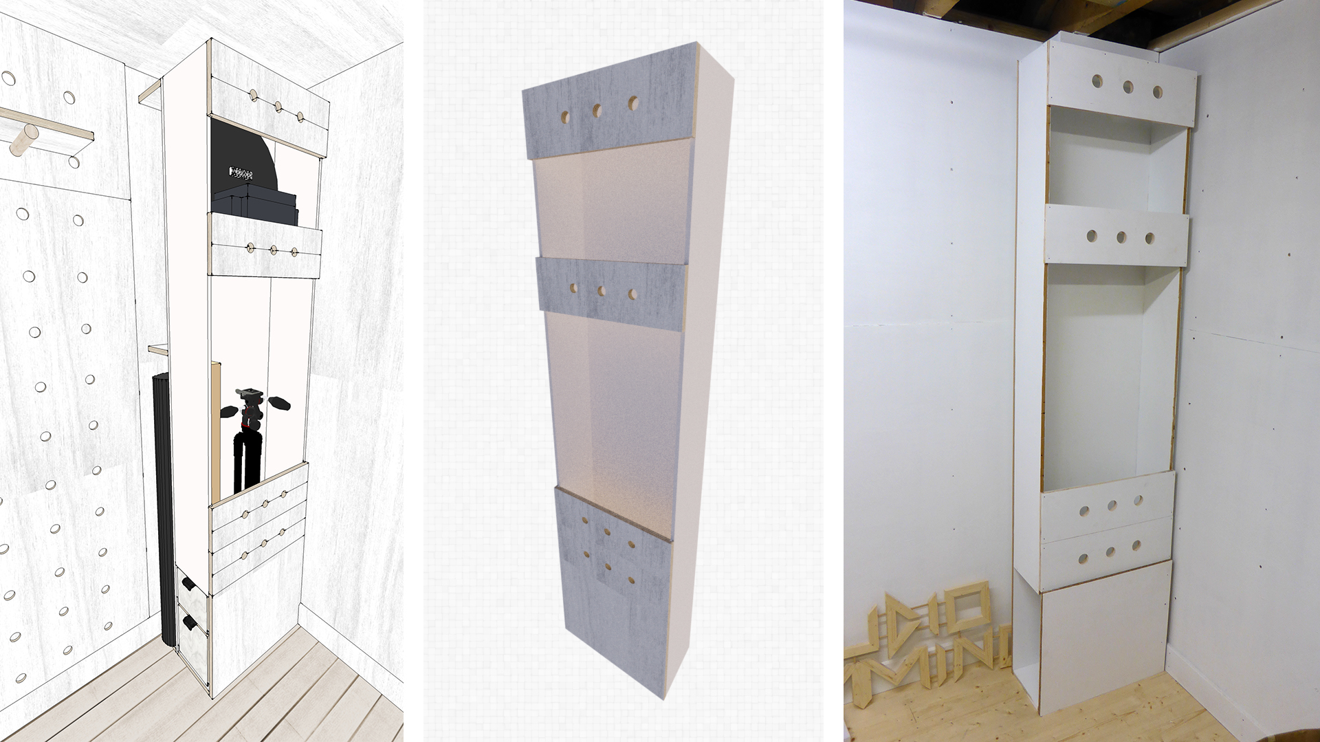
Above: And finally after three days, we have something worth showing! It's not the prettiest, and it's certainly not a fine bit of woodworking; but after the problems we encountered I'm very happy with the (not quite) final result. Still to do, obviously, are the two drawers and the rear cubby holes. We will also need to paint the edges of panels white. With regards to the drawers, we have kept the bottom front panel loose so that we can actually fit these drawers in later; that's why it looks a bit odd.
Now, if you'll excuse me, I need to have lie-down! Progress will likely be sporadic for a few weeks as not only am I pretty much out of materials and things I can do at present, but I also have another diorama to build before the end of the year! I will however try and get the drawers built at least, and maybe even add those LED strips to the new sign in the not-too-distant future.
Day Eighteen: Finally finishing the 1st storage unit
Well, this has certainly turned into one of those projects where nothing goes to plan. The rear panel not quite being cut straight resulted in everything else being wrong (even though they were cut out and machined correctly!). Certainly a lesson of double and triple checking everything, and never assuming a bit of wood is straight...
Regardless, we got there in the end, so let's take a look at the final part of this units' construction (and yes, we hit yet another problem or two on the way!):

Above: Before we can attach the lower front panel, we had to cut and assemble the drawers, and fit the drawer runners. Whilst I would of course chosen to use the Skilsaw, my Dad is obviously a man of tradition! Note that only the front panels and bottoms of the drawers will be cut from 18mm ply; the rest will be 9mm to save weight and make the most of the limited space available.

Above: And now it's down to me to machine the rebates in the two front drawer panels. Marking out these rebates correctly is crucial, and must be worked out by subtracting the width of the drawer runners when complete + a couple of mm extra to allow a bit of wiggle room. The rebates are 9mm, and as I only had a 6mm bit, these were done in two halves.

Above: Whilst I was doing the machining, my Dad was securing the drawer runners in place. We actually used two different varieties (as we had them spare). This lower one was simple as each side was one piece. This did however mean that we needed to drill a hole in the bottom of the storage unit (right hand photo) to enable us to get a screwdriver in there later to attach the drawer itself; as it did not extend far enough out. Note that a bit of wood is clamped on the opposite side to the bit we are drilling to reduce the likelihood of wrecking the ply.

Above: As I was still machining, my Dad was cutting up the rest of the components needed for the drawers. This time we have some spare 9mm ply for the sides and back pieces. Using a Skilsaw on the longer sides speeds things up.

Above: With one drawer front machined, and a tongue formed on one of the drawer bottoms, we could glue them together. Worth noting here is on the rebate at the front of the image; you'll see that I've rebated further in than the original line (you can see my test plunge under the "A" in "Drawer Front"). The reason for this is because I want the fit with the 9mm ply to be nice and tight, so I tested it with a scrap piece after the initial test plunge, and adjusted the router accordingly.

Above: To provide further strength, and to help us build the drawer quickly, we chose to hammer in some 30mm panel pins in addition to gluing the components together.

Above: And here is the (almost) finished first drawer. As we're using two different types of drawer runners, the two drawers actually differ slightly to account for the variation in runner widths/heights.

Above: And here we can see the two styles of drawer runners. The second is more of a traditional drawer runner, and is actually (in my opinion) harder to fit due to a number of reasons. One of which is that the screw holes are within the runners themselves. This means that they have to be flush with the surface; not an easy thing to do when the only screws you have that are short enough have big heads. In the end we actually had to take them off and drill out the holes with a larger bit. But that's not where the difficulty ended...

Above: Another problem was that these runners had metal tabs in the wrong places. These had to be bent by 90 degrees to allo us to fit them to the bottom of the drawer.

Above: In order to make sure the drawers stopped flush with the front of the storage unit, softwood blocks were nailed to the back of the drawers. I also drilled a hole and inserted some 6mm dowel (left-over from the sign we made last week) to act as really simple handles.

Above: And that's when things quickly became frustrating again. We noticed that the front lower panel was not sitting correctly. After a lot of time spent troubleshooting, we realised that not only were some of the tongues on the unit itself too wide to fit into the rebates, but the whole bottom end of the unit was warped (the arrow shows the direction, but it wasn't quite that curved!). We eventually managed to cut enough of the tongues width away to get it to fit (with some persuasion with the clamp), but that's where things went from bad to worse...

Above: Try as we might for half an hour in the cold (by this point probably about 4 degrees C), we could not get the top drawer in. We did eventually realise that one of the runners was too high, but even after fixing that it would still get stuck. Incredibly cold and annoyed, we left it for the day, and came back to it the next morning, well, Dad did! As you can see, to fix it he simply rebated the sides of the top drawer by 2mm, which seems to have solved the problem by adding more side play. Note that he started painting the drawer fronts, and you can also see the expanded holes in the drawer runners to allow the screws to sit flush.

Above: Finally, the unit is complete! My Dad has been busy painting the visible edges (it's still drying in these photos), and I think the end result is very smart. It really should not have been this stressful to build (the table certainly wasn't), but it just goes to show how incredibly important it is to never make assumptions when marking and cutting out components!
And now progress will be practically non-existent probably until next year sadly. As much as I'd love to make the most of the space and get all my stuff put in, without a ceiling, the new window, and only one working socket, it's just not possible. Mornings especially are still incredibly cold in there!
There may be the odd bit of progress to share, but if not before, we'll be back...
There may be the odd bit of progress to share, but if not before, we'll be back...
...in 2021...
Day Nineteen: General Update (window, lights, electric)
Can you believe that it has been over 4 months since we started this build, and only 4 days short of 3 months since the last bit of progress?! It's a combination of many factors; most notably lockdown, me continously forgetting to order the new window, as well as working on various commissions.
The good news is:
- The electrician has already come around to cost up, and he'll be carrying out the work over the next weekend.
- The window has finally been ordered, and is due to arrive on the 9th March (two weeks from the day I'm writing this).
- The lights have been ordered, and have already arrived (more on that in a bit)
The bad news is that costs have escalated significantly because:
- The whole consumer electric unit in the house needs to be replaced. As it's made of two units due to a later extension to the house, it seemed the right time to get it all updated to code, as well as condensing it into one unit.
- The garage consumer unit also needs to be replaced (not surprising as it was installed 20+ years ago).
- The armoured cable from the house to the garage also needs replacing which is a bit of a nightmare not only because there's a new-ish lean-to that has been built on it, but also because that means the new ethernet cable will have to be routed in the same new trench; ethernet + power cables is not a good combo, so I'm a little worried about that!
- The original window I was going to get was out of stock (even though it's made to measure! 🤷), so I decided to buy elsewhere and instead go for triple glazed rather than double glazed, as well as having the window fitted with an emergency egress. I almost went for a black window to match the fascias until I saw the additional cost that incurs!
Window
Since this is a general update and I have very little progress to show, I thought I'd show the current state of the window, and hence a major part of why it gets SO cold in the garage even with the new insulated walls and floor. As I mentioned elsewhere on this page, my dad built this window over 20 years ago when he worked as a carpenter/joiner for a portable building firm. It's certainly well built, but after 20 years of having had no maintenance (judging by the two thin layers of paint, it has had one repaint from blue/green to white), it has become rather rotten. The top and edge of the sill plate is basically sponge at this point!

Above: The putty holding in the glass...well... barely holds itself, let alone the glass! Worringly, there is moss absolutely everywhere; outside and in. Oh, and I don't remember the last time the windows were opened, and I for one don't even want to try opening them until it comes to taking the entire window out!

Above: With the single glazing and waterlogged woodwork, I think it's easy to see why it needs replacing, and just why it gets so cold in the studio at present! Still, not bad for 20 years unmaintained.
Now, whilst the window is being manufactured, my attention turned to what I could use for an internal window sill, and I spyed a suitable length of wood outside. This was actually originally part of a window A frame for a canal boat; my dad rebuilt the whole assembly from hardwood as a job for a family friend. Anyway, the old length seemed to be in decent enough condition, and with the patience of a saint, my dad starting chiselling away the thick layers of paint and primer.

Above: Surprisingly, it doesn't appear to be hardwood, and feels more like a high quality pine board. Whatever it is, it'll do the job nicely once we've fully dried out the edges. Once the new window is in, we can cut it to size, do any machining, sand it all down, and give it a wax finish or similar.
Electric
As already noted, basically all the wiring has to be replaced, including the main armoured cable going from the house to the garage. As I'll also be installing an ethernet cable so that I can get internet into the studio, a trench had to be dug before the electrician comes next weekend.

Above: Thankfully, we're going to be redoing this section of garden at some point (hopefully in the summer) to be mostly patio instead of having this crumbling concrete pathway and tiny bit of (rather unusable!) grass. You can see the current black armoured cable running down the side of the house, and sharply turning into a little metal conduit/junction box set into the concrete. This will all need replacing.
Dad managed to cut the concrete path out, and we removed all the dirt, hardcore, and rubble. To stop anyone falling into the trench we've put some old slabs and wooden sheets on top for the time being. Hopefully we can get the power and ethernet in the same trench, but I am worried about interference so will have to consult the electrician tomorrow.
Lighting
You may remember (Days 13/14) that I originally planned to fit 6 LED downlighters in the studio. Whilst that would've been fine, it suddenly occurred to me that perhaps some LED panels, like I use for photography, would offer greater and more even light output. I then found out that there are companies that supply large LED panels to replace the old flourescent types you find in the suspended grid ceilings of offices. What's more, they also offer surface mounting kits, and the panels come with their own drivers. After much thought and research into different sizes and their cost, I decided on the following:

Above: As you can see, I settled on three 600mm x 600mm panels, of 5000K (daylight) temperature. These are positioned to focus on the areas (A, B, & C) where light is needed the most. Being surface mounted, I no longer need to worry about the position of rafters, so I can fit the panels onto the ply ceiling exactly where I want them.
Each of these LED panels will give about 4000 Lumens; a vast (4x total) improvement on the 500 Lumens of each LED downlighter:
- 3x 4000L = 12000 Lumens total for LED panels
- 6x 500L = 3000 Lumens total for LED downlighters
That of course means I should have TONS of light for photography, but for when I want less brightness, I've purposefully gone for dimmable drivers; combined with a 1-10V dimmer switch on the wall, I can adjust the light to suit. This will be a much better system for my line of work!

Above: Here is one of the three necessary dimmable drivers (A), the dimmer switch (B), and one of the three surface mounting frames (C). Note the instructions on the right which as you might be able to tell make for a quick and easy set-up. Three of the four frame sides are assembled and screwed to the ceiling, the driver screwed in the middle, and then this is connected up to the LED panel which slides in place on the bottom (wider) aluminium runners. Then the last side is simply screwed into place. Sounds easy in principle, so let's hope it is as easy as it looks!

Above: And here is a photo of one of the three LED panels. A very decent size! The arrow points to the "plug and play" power socket which will connect to the LED driver.

Above: And for completeness, here's a new render showing what I hope the finished studio will look like. NB. I've given the LED panels a yellow tint just so that they stand out more in the render.
So, all in all, very little physical progress to show for the last 3 months, but it's looking like I'll be able to move into the studio by early March; exciting!
Days Twenty & Twenty-One: Wiring & Ceiling
It has been quite the productive weekend! The electrician has done sterling work, and it's clear that it is always worth contracting specialist areas like electrics, as not only will it give peace of mind, but you get it done properly. Whilst the electrics has not *quite* been completed, it is very close to being finished. All this despite having to:
- Tear out and replace all the fuse boxes both inside the house and in the garage
- Rewire the studio/garage
- Install LED tubes and about 6 sockets in the workshop (plus associated wiring and an additional fusebox!)
- Remove the armoured cable and replace with a new one, complete with earthing cable
- Install the cat5e ethernet cable in the studio (it isn't yet wired up to the house because I need to get some new conduit)

Above: By 5pm Saturday (after having already completely wired up the entire workshop, including a fusebox), the electrician and his apprentice had removed most of the old cabling, and run the new wiring to where it was required. There is one section at the bottom of the photo that still needs a junction box to wire it to the existing socket off-screen, bottom right. (This was done today (Sunday)).
It looks a relatively simple job, but there's a lot of methodical thinking that has to be done, and I for one am glad I didn't have to figure it all out. Note one of the cables for the LED panels can be seen curled up on the left.

Above left: The only cable we hadn't allowed for (thanks to my dodgy memory) was the cat5e ethernet cable. The bottom wall panel was in place, but fortunately we had run out of ply for the top panel 3 months ago. That meant we could still put a bit of string behind to act as a feeder for pulling the wiring through. After Dad gave up trying to drop the string down with the help of gravity and a threaded bolt, I opted for loosely taping the string to the end of a metre rule, and forcing it through the insulation in the wall. That, much to Dad's partial dismay, seemed to work; and I could pull the string out from under the tape, and through the hole. A pencil tied on means that we won't accidentally undo that progress!
Above right: We had already cut out the holes for the socket boxes, and drilled holes in the studs for the electrician to run the wires. We also made sure that the relevant wall panels were only held in place with 4 screws so that they could be easily removed for wiring it all up. Every little helps!

Above left: We had already installed the box for the cat5e ethernet, but the electrician had to figure out a safe way to route it through the stud wall avoiding the power cables, which are close by due to the light switch placement.
Above middle: The new armoured power cable has just been put into place, and is being wired into the fusebox. Unfortunately, we ran into some trouble routing the new cable into the existing holes in the house as we're running an earthing cable as well, so we won't have power into the garage/studio/workshop until next weekend. Note the old armoured cable to the left, going under the patio.
Above right: This is (most of) the redundant cabling and fuseboxes. The latter is all crammed into the front box, the cabling is the centre box, and the two recycling bags are full of cardboard from all the new kit that has been required; and that's after I spent an hour cutting it up and flat-packing it!

Above: Going back in time for a bit (whilst the workshop was being wired up on the Saturday morning), Dad and I went about marking out and cutting the 12mm ply for the ceiling panels. This photo shows that we're using off-cuts of the 1220mm wide ply (having previously cut them to length so that the ends sit in the middle of a joist) to work out where each sheet will end, and marking the joists above as we go to help us measure it all out.

Above: As always, the trusty Skilsaw comes in handy, and makes cutting the ply sheets an easy task. (Don't worry, I took the photo quickly so that I could hold the two pieces before Dad had made it all the way to the end!)

Above left and right: Right after the electrician left on Saturday, we donned masks, hats, and gloves to put the insulation in the ceiling (at last!). This was as dusty as you'd expect, and it didn't help that I genuinely couldn't see what I was doing due to my mask steaming up my glasses! It didn't take long though, and what's more we even had two spare rolls that Dad could use in his workshop ceiling.

Above: On Saturday night it suddenly occured to me that I had planned to paint the ceiling boards white BEFORE we put them up. Thankfully, I wrote a note to remind me to do it on the Sunday morning. This photos shows the three main ceiling panels, after I had rollered on the first coat of paint. It's a good job the weather was beautiful this weekend!

Above: Now that the wiring and insulation had been put where it was needed, we used these "deadmen" to shimmy the ply up to the ceiling. Our dimensions weren't too far out, but as it turns out, none of the three pillars in the corner are square, which meant we had some frustratingly difficult adjustments to make...

Above: Always drill pilot holes; they'll save you a lot of hassle! The multi-tool on the right is an invaluable asset when it comes to making adjustments in awkward locations. Unfortunately, it is one of the loudest things on the planet, I swear!
By the end of Sunday, all three main ceiling panels were up; with just three tiny bits to put up on another day. Sadly I don't have a photo (the studio is a complete mess so not exactly photogenic at the moment!), but suffice to say I'm very happy with the progress made this weekend.
Next Saturday (6th March) will be spent finishing up all the electrics required. The electrician is a family friend, and willingly came out over this (and next) weekend to get this done for us, despite also working throughout the week elsewhere. I've not heard one complaint out of him, and whilst we've tried to make his life as easy as possible by setting up what we could beforehand, it still hasn't been an easy job for him (to say the least!). It's already been worth the expense, and I haven't even got my studio space done yet!
Day Twenty Two: Final electrics, ceiling panels & skirting
It's been a week since the first electrics went in, but I'm happy to report that, aside from some minor things inside the house that need adjusting (i.e. my bedroom light; which hasn't worked for a year!), the electric is complete and signed off as meeting current regulations.
Getting to this stage has not been easy, but more on that in a bit. First, my Dad was to be found outside cutting up and chamfering the final bits of skirting board.

Above: I originally didn't think I'd bother doing the areas where Sandy Shores and all the modelmaking bits will be stored, but in the end I liked how the skirting board finishes off the room, and hides any gaps between the walls and the floor. Leftover bits of MDF were pressed into action.

Above: This photo shows the large big piece for the window wall; this was cut and painted months ago, but as the wall panels behind needed to be removed to allow the two double sockets to be wired up, it wasn't fitted until now. Note that the carpet is an offcut (I use it for exhibitions!), and is only there temporarily.

Above: This montage shows the final ceiling panel that was needed to finish it off. Nothing complex; just a bit of 12mm ply. As we had trouble due to the pillars not being square, I measured every dimension to ensure it was a good fit. The difference from one end to the other end of the pillar is almost 10mm! Good job I checked this time...
...moving on, and like I said at the start, the whole house and outbuildings have been brought up to the latest regulations; complete with new earthing rods and cables, and all-new fuseboxes throughout. We had a lot of trouble trying to route the new armoured power cable through the ceiling above the kitchen (it was a long and arduous affair), but finally it's all done and dusted!

Above and below: Before the electricians arrived today, Dad and I saved them a bit of work again; this time by assembling the frames for the LED panels, and then screwing them to the ceiling in the right spots. I've adjusted their position by about 10mm to the door side; this is to make sure we can slide the panels in without it being too tight to the wall. Then it was a case of working out which side to put the drivers (so that the plugs from the driver and panel can easily stretch enough to slide the panels in), and screwing them to the ceiling as well.


Above and below: The electrician wired all three up in no time at all first thing this morning. The photo above shows that the surface mounting frames allow plenty of clearance for the driver and wiring. The photo below shows all three LED panels in place. All that's left to do is screw in the final frame piece on each. Very smart!


Above: With that done, the bulk of today was spent setting up the ethernet (Cat5e) cable and associated conduit. This is done in 25mm semi-flexible PVC conduit, and is properly sealed with rubber rings on all boxes, and sealant along every joint. I am, however, in a bit of trouble; my parents (and to be honest, myself included) are not exactly thrilled with the bright white conduit that snakes along the garage, then around the front of the house; thus I've been tasked with finding a way to paint it to match the brickwork (or failing that, black - to match the garage fascias)... either way, it has been put up very well; the electrician even used spirit levels to ensure it was all perfectly aligned and level - now that I didn't expect!

Above: We have also noticed that the LED panels do not dim; I can't be too annoyed at the electricians as they have been absolutely amazing in every other area, but at the same time I did ask them to check due to the specific way these particular panels need to be wired to the dimmer switch. Hopefully they can remedy this on their final visit on Saturday... for now though, I'm happy because the panels produce an amazing amount of light; it's hard to tell from the photo because the camera automatically adjusts (I'll do a proper comparison tomorrow, without the ply in the way as well), but the difference really is night and day from those old fluorescent tubes!
Aside from that bit of minor remedial work to do, all in all the electricians must be praised as they've genuinely gone above and beyond for me and my parents. In any case, I have gone over most of the walls with another coat of white paint, which means that all that's left to do is:
- The window (hopefully on Tuesday, but we'll see)
- Cut, machine, and wax the board for the window sill
- The two missing wall panels
- The shelving in the storage alcove (left in the photo above)
- The 3 pegboards (one each side of the window, and a large one across the entire rear wall)
- Trim for the window and door, and coving to hide the gap between walls and ceiling
- Complete the sign!
- Sand and protect the flooring
- Buy and fit the blind for the window
And whatever else I've forgotten!
Days Twenty Three to Twenty Six: Pegboards
Since the last update, more materials have arrived for the studio, including the brand new custom triple-glazed window (not cheap, but it's worth doing it properly). Unfortunately for you guys, I'll be showing off most of these materials, including the window, another day (so that there's enough photos about them to make it worth your while).
Today (16th Mar), we made a start on the pegboard. Surprisingly it's taken about 5 hours of the day; due to both the set-up needed, but also the somewhat tedious nature of the build. For whatever reason, the only easily bought pegboard is the 3mm (or so) thin hardboard type. This isn't going to cut it for anything other than decorative use, so the only option was to make our own...

Above: Simply drilling holes in the wall wouldn't really be a good way of building pegboard - even with the 18mm plywood walls that we have. For starters, the dowels (pegs) won't be glued in, nor will every hole have a peg in it. Thus drilling holes in the wall would mean you'd see the insulation within it. Sure, you could drill only partially through, but that means less peg in the wall; which also means a weaker design. To combat this (and also hide the existing wall join between the upper and lower panel), I'm making the pegboard from yet another sheet of 18mm plywood! As always, the first step is to cut it to the right dimensions with a Skilsaw.

Above: Each hole will be spaced equidistantly from both each other, and the edges of the board. Thus a sliding square is extended to 100mm, and lines drawn around the perimeter of the board.

Above: From there, it's a case of drawing a grid of 100mm squares. See if you can spot the two slightly wider squares along the centre of the board; unlike my original plan, we decided to use the full width of the 1220mm board. This obviously doesn't divide equally by 100mm, hence the wider "squares" in the centre.

Above: The dowels I bought were supposed to be 18mm. Spoiler alert, they aren't! They are actually 15mm diameter. Well, not ideal, but it should be thick enough for what I want. Anyway, we can see here that my dad is trimming a short length of dowel. Why you ask? Well, the closest router bit we can find to 15mm is 12mm! Thus every peg will have to be slightly reduced in diameter on the last 18mm. But what do we need this short peg for now?...

Above left: ... ah, well, we obviously need a jig to help us cut the holes accurately. I had already decided that since we have the use of a router, we were going to use it instead of a battery drill. I figured it would be much easier to make perfectly vertical holes that way; something crucial for pegboards to work properly! The left hand photo shows the jig that Dad came up with. 1 is irrelevant (guess how we realised the wrong dowel was bought!). 2 is the peg - the narrower 12mm end is sitting in a 12mm hole, which is spaced 100mm (centres) from where the hole under the router bit is. The router mark at 3 has a similar one on the far side of the router base, which Dad used to align it with the grid markings. 4 shows the two screws securing the router to the jig.
Above right: The wider shot on the right should help clear things up - the peg is removed after every hole is made, then the whole jig moved to the next mark, and the peg dropped into the hole just cut. That automatically sets the correct 100mm spacing ready to plunge the next hole. I did say to Dad that to save him manually lining up the other end, he could've drilled a third 12mm hole at another 100mm distance on the jig, and dropped it into the next hole. Regardless he seemed happy enough lining it up manually.

Above: After an hour or two of routing, my Dad had finished. Here, the last row needs doing. (He did manage to cock this up because he got complacent, so the middle row is off-centre now because he forgot he needed to adjust the jig for the wider centre row. It's a mistake easily done when you're doing tedious work like this.) Nethertheless, after 198 holes routered, I think I owe him a beer or two!
THE NEXT DAY...
Due to supposedly being the first nice day in weeks, we were planning to remove the old window and fit the new one today. Unfortunately, Dad was called away to help a family member at the last minute! In the end, it turned out to be a very grey day, but at least there was no rain; looking at the forecast, the weather seems to be much the same for the forseeable future. We'll see if we can fit the window tomorrow...
Anyway, since Dad wasn't here, it meant I had 'fun' wrestling a full sheet (2440 x 1220mm - so probably about 25kg) of 18mm ply on my own! I did manage to drag it onto the trestles, so it was time to cut it into more managable chunks...

Above: After a bit of planning to work out what I needed cut out from the sheet, the sizes of those bits, and how best they would fit to reduce wastage; I began marking them out. As the spirit level (it's a handy thing to use as a guide for the Skilsaw) is not quite long enough to span the entire 2.4m length sheet, I had to get creative. I decided the only real solution was to clamp a block of wood at the right distance from the edge of the board. As the other end of the spirit level is clamped, the Skilsaw will push against it from the right side, and thus also against the clamped block of wood in the photo; i.e. the spirit level won't be able to move so long as pressure is applied against it when using the Skilsaw.

Above: Eventually (after much wrangling with the sheet of ply and the trestles), the two smaller pegboards were cut to size. When using metal trestles especially, you need to check before you make any cuts to make sure the trestles aren't in the way; hence the constant moving around of the board. Anyway, we can see the grid formed from 100mm squares is present on both sheets (900mm x 500mm).

Above: I forgot to take close-ups of the centre recesses in the router yesterday; so here they are. These help line up the router with the centre markings. Note that only the rightmost one (at the front of the jig) is needed once you've done the first hole; the other two are automatically lined up by the peg resting in its hole.

Above: Thankfully, I took so long wrestling with the sheet of ply and being careful when cutting it, that Dad had arrived back just as I had the router set up ready to plunge the holes. Above you can see that I've lined up and clamped the jig for the first hole on one of the boards. After this hole is done, you won't need the clamps for obvious reasons.

Above: Dad kindly did the rest of the holes for me (in the meantime, I was painting some of the other panels I had cut out earlier in the day - more on them in another post). By the time I was done, he had finished the boards, so it was time to paint these as well. All three pegboards, including the large one made yesterday, will need at least one more coat of paint before being put on the walls.

Above: With the panels done, attention turned to the pegs. I decided that a range of lengths would probably be handy, so I settled on 150mm, 200mm, and 250mm lengths. I had bought 4x 2.4m lengths of the dowel, so settled on quantities of 10, 20, and 15 respectively. Cutting these was a doddle with the cross-cut mitre saw. A wood block (left) is clamped to act as a stopper, and chop - in one smooth motion the dowel is cut to length! The distance between blade and block is the length of the dowel... obviously!

Above: As we have 15mm dowel, but only 12mm diameter holes, the ends of each dowel needed to be trimmed on the lathe. A mark was drawn on one end of each dowel. We decided on 17mm in from the end (rather than 18mm to match the ply thickness) to give us one millimetre of leeway.

Above: Once you get the lathe set up to take off the right amount (i.e. so that the dowel is a snug fit in the holes), you don't need to touch the wheel that moves the cutter forwards and backwards. Once the dowel is in (centred properly, of course), it's then a case of setting the cross slide to automatically move to the left, trimming as it goes. The cross slide engages via a lever (a clutch that connects with a rotating threaded bar). This is then disengaged once the full travel (i.e. 17mm in this case) has been reached, and the cross slide manually moved to the right again. I love lathes (although I let Dad have fun with it today) - they are incredibly satisfying to use!

Above: By the end of the day we had all 45 pegs cut to length, the ends trimmed, and any excess (splinters etc) sanded off carefully.
All that's left to do now with the pegboard is to hang it on the walls, cut some shelves, and make a holder on the wall for the pegs themselves.
THE NEXT DAY...
Well, whilst the weather was dry enough in the morning to make us think about puttting in the new window, the wind was strong, and the clouds ever-darkening...
...thus today was spent mostly painting (outside in the morning, then inside from the afternoon onwards due to the onset of rain). Before I had even gone out to the studio in the morning, Dad had already been busy screwing on the penultimate wall panel that I had cut yesterday, and adding some draught-proofing. I'll show these another day, as I'd like to finish showing the pegboard today.

Above: Putting up the smaller pegboards was easy. First, we worked out where they would sit (on the centre of the walls), by subtracting the pegboard width (500mm) from the wall width (660mm) = 160mm, then dividing by two. That gave use an 80mm gap each side. Using a spirit level, the side lines were marked perfectly vertically. That meant all we had to do was line the top of the boards with the top of the window surround, drill pilot holes, and screw the panel up.

Above: The same needed to be done with the big panel (1900mm x 1220mm), although being that much heavier and harder to handle meant using some blocks (cut to appropriate lengths) to stand the pegboard on top of ready for drilling/screwing on.

Above: And that gave us our three pegboard panels (one out of shot to the left, on the other side of the window). But wait. Something caught my eye that looks out of place...

Above: ...how we didn't spot this sooner I've no idea, but it made me laugh to realise that somehow we had missed one of the holes! (Dad said he blames the pattern making his eyes go funny when routing them in the first place). Nevermind, thankfully we hadn't yet diassembled the jig from the router, so a quick lining up and the hole was made!
THE NEXT DAY...
Yes, the fourth day into the pegboard build. Truth be told, whilst it has taken longer than I was expecting, we've also been busy doing other things (mainly painting) in the studio as well. Again, we'll get to that another day...
...anyway, today I was working solo as Dad was busy building a new door. I had one simple thing planned for today; building a wall holder for the pegs.

Above: The first step is to cut a length of 32mm x 32mm PSE softwood into four 130mm lengths. As you can see, this wood was salvaged from a past project - one of two now dismantled model railway layouts! Once the bits with holes in were cut off, and the lengths cut with the compound mitre saw, I gave them a good sanding with a belt sander to remove all that old glue. The other three sides were also sanded back a little to give a better surface for painting.

Above: Speaking of painting, the vast majority of my time today was spent doing exactly that. All blocks received two (maybe three, I honestly can't remember!) coats of white paint. As per yesterday, the placement of these was marked out to ensure they sat level, were aligned with the top of the pegboards, and were equally spaced. The right hand photo shows that pilot holes have been drilled into both the blocks and wall. Note that I've pre-screwed the blocks so that a tiny bit of screw is poking out of the back; since there are holes in the wall, this makes lining it up that bit easier.

Above: The four blocks aren't there just for support; they are also there to separate the 3 types (different lengths) of pegs. The placement of the screws in these blocks is actually important.
Note the inset image showing a closeup of the left side of one of the blocks:
- Just to the right of the screw is a faint vertical line showing where the upright will go up to.
- The screw is purposefully located as close to the vertical line as possible so that it remains hidden, but allows enough room for...
- ...the screw that will secure the upright in place. Hence the 14mm is the position from the left (or right for the other side) that the uprights' screw will go.
Much easier to show than explain! Basically, I want the block screws to be hidden behind the uprights, but I want to leave enough room to avoid screwing the uprights on top of existing screws.

Above: And that is about it. A simple but effective peg holder. Sure, you could just put them in pots on a shelf, but this way; a) I make use of the vertical space on that awkward pillar, and b) I won't have to dedicate a shelf to them, and potentially accidentally knock them off! Incidentally, I'm thinking of chopping the long (250mm) pegs in half; I don't really think I'll need any of this length, whereas early tests so that shorter ones seem to be more useful.

Above: As I was tidying up at the end of the day, I couldn't help but put some pegs into the boards to try them out. This is going to be such a useful storage space; everything will be super easy to access, unlike previously!
All that's left to do is to cut up some shelves, and the pegboard will officially be complete. In any case, it's so nice to see that, finally, the room is actually starting to look like a studio; it won't be long before I can move in - how exciting!
Day Twenty Seven: Window Installation
11 days after the new window arrived, the weather finally graced us with some sunshi... wait, no, it let off in the wind/rainy department! That meant, after initial trepidation (Will the weather last etc!), that today was the day to do the window...

Above: ... but the first job, obviously, was to remove the old one. We were expecting this to be an absolute nightmare, but it seems the rain (mixed with the unmaintained frame) seems to have done its worst on the woodwork. In actual fact, the little hinged toplight didn't take kindly to be opened... it turns out the hinges on both openable windows were absolutely rusted through. Needless to say, the window completely fell out, smashing on the ground below! The inset photo shows one of the four hinges. The white squiggly line denotes the section of hinge completely rusted off. And yes, the big window also fell out, but I was outside to catch it this time.
I did say the other day that I was worried this would happen if we ever opened these windows (can you tell they haven't been opened in at least 10 years!

Above: Unfortunately for this poor old window, it met a grisly death; as it's all wood, the easiest way is to attack it with a saw and a hammer. I would say that they made light work of that, but truth be told, the lovely joints Dad made when he first build the window 30+ years ago were remarkably strong considering they were all wet through)!

Above: The last sections were cut out (left), revealing some lovely looking wood on the only dry area. That is, until you look at the joints and see (inset photo) the sodden, rotting woodwork! And on the far right you see a lovely, and surprisingly still-intact, aperture. Note the steel lintel that was thankfully present above. You can also see the new interior stud wall.
Taking photos was hard (i.e. there aren't any, sorry!) whilst we were both manhandling the window in, using packers to get it sitting level. We did have to take the bottom cement layer off the outer wall, but thankfully after that the window went in trouble-free.

Above: Just visible on the thin left photo, we've got some temporary wooden battens. These set the depth that the window should sit to, and it means I can pull against the window whilst Dad screws the window into the walls. The left pane is obviously the opening window, and care must be taken to "toe-and-heel" the window to prevent it dropping over time due to the excess unsupported weight (when open). As the hinge is on the right, the top left corner and bottom right corner (see black arrows) are packed first to provide a stronger diagonal force. Then the rest of the packing can go in (less packing is needed in the opposing corners). Once it's level and square, the glazing beads are knocked into place (supposedly with a nylon hammer to prevent damage/scratches, but in our case...) using a block of wood covered in masking tape, and a mallet (see inset photo). This is designed to be very tight so as to provide a good seal, but it feels very unnatural hammering so hard around glass!

Above: Before we seal the window in, let's put the air vent covers in (both inside and outside), and fit the end caps onto the window cill. With that done, we can put the window sealant into the gun, and squeeze away. This is required all around the window (obviously!), and also around the outside vent and window cill. To finish off the installation (bottom photo), a new mortar mix was applied underneath the cill.

Above: With the building now watertight again, it was time to head inside. You may remember (top photo) the wooden board that Dad painstakingly stripped all the paint from a while back; well, a few weeks ago I went ahead and sanded it nice and smooth with a mouse sander. Took ages, but the various stages can be seen in the lower three photos here. It really came out lovely!

Above: Then we could cut the ends off (they had holes), and also cut off a section from each end; we want a nice window cill that will wrap around the walls as the photo above shows. Due to nothing being square in this building, we made sure to check all measurements - there's about a cm difference in width from one end to the other, so it's a good job we checked! Anyway, I have exposed screws all over the studio, but I wanted this board to be a focal point of the room. That meant drilling some larger holes, and using the wood we cut off to produce some pegs to fill the screw holes in with. The peg cutter bit on the right photo is a hollow bit; simply drill it, then snap off the peg inside with a screwdriver...

Above: ...and then glue the peg into the large holes in the window cill. Because we matched the drill bit size to the internal diameter of the peg cutter, it fits perfectly (just make sure you orient the woodgrain of the peg to the board). Once the glue has cured overnight, the excess is chiseled and sanded off, and hey-presto, we have a beautiful window board!

And "that's it" for today. A huge, huge milestone in the studio build. We now have an incredibly warm room, with a window that is not only openable (and won't fall out!), but also doesn't have an annoying frame at eye level. That means I also get a nicer view; not bad for a day's work...
Days Twenty Eight & Twenty Nine: Floor varnish & trim (Pt.1)
There isn't much to show for two days of work, but trust me, we did make progress; it's just that the vast majority was either sanding or painting - either of which are exactly fun to photograph! Let's have a look:

Above: I mentioned a few days ago that we had multiple materials arrive; well some of that included some door stop trims. Rather than use these for their intended purpose, we used them as a form of coving to hide the gap between the walls and ceiling. Obviously I wanted to paint them first before putting them up to avoid neck ache where possible, so these all had at least 2 coats of paint on the visible edges first; I painted them, Dad (as you can see here) is nailing them to the walls. As you can see, that still leaves some ugly gaps on some walls (see right hand photo)...

Above: ...so Dad came up with a plan; use some filler 'paste' (i.e. it's in a gun/tube, rather than normal filler). Simply squeeze it in the gap, smooth over, let it cure, then paint! This was applied to any corners that had visible gaps. All of it has since had 2 coats of paint on, but will require one more, I think. These, along with the coving, have made a surprisingly big difference to the overall look of the studio. It's not going to win any awards (especially with all those screws visible), but I'm over the moon with how it's looking!

Above: Another odd job to do was to cut some shelves for the pegboard wall panels. Using two offcuts of 12mm ply, I went with a variety of widths (to fit the pegs) and lengths as multiples of 100mm. That means we have some 100mm wide, some 150mm wide, and some 200mm wide. Length-wise, we have some 200s, 300s, 400s, 500s, 600s, and 800s. There was no real rhyme or reason; other than I was just trying to have a good selection, and make the most out of what would fit on the scrap ply. As with seemingly everything else in the studio, these were all given at least 2 coats of white paint (two on the underside, and three on top). I'm yet to decide whether to paint the edges, but I think we do need a bit of colour in the studio!

Above: Moving on, we have also tackled the wooden floor. This obviously meant taking everything out of the studio, and borrowing an orbital sander to get the job done quicker. Dad and I took turns (with appropriate masks on!) and we went to work sanding the entire floor. As you can see, we had a large stack of sanding discs at our disposal, but in the end only needed two for this.

Above: The top two photos show when I was in charge of the sanding. Note the dark patch in the middle of the floor - this is two show the vast difference between the muddy state that the boards had become, and the nice sanded areas around it (see close-up on the top right). The bottom two (plus inset) photos show that whilst I was busy with the never-ending job of painting everything white (seriously, it's all I've done the past two days!), Dad was kind enough to brush on the gloss floor varnish. This goes on a milky colour, but as you can see gives off a lovely sheen (although in the last photo it is still drying, so the end result isn't quite that shiny).

Above: As the weather was so unexpectedly nice today, we actually managed to get the full three coats of varnish on, before sunset!

Above: And a slightly different set of views showing the sudden warm colour that now compliments the window board; much better than that muddy scuffed floor! And speaking of colour, there will be a sudden influx of colour soon; but more on that next weekend, when the object in question arrives...
...I'm such a tease!
Click to go back to the top of the page
Days Thirty to Thirty Two: Trim (Pt.2), monitor shelf, roller blind, & acoustic panels (Pt.1)
The studio nears completion, and actually as I type this I can reveal I have officially "moved in"! The space is as wonderful as I had hoped, and the peace and quiet is lovely; I'm sure to reap the benefits from this studio for years to come, and I can fully test it out when it comes to starting my next diorama commission on the 1st April.
Anyway, the saga hasn't quite come to a close, so let's carry on with the updates!

Above: ...first up, part of the recent haul from Wickes were some pre-painted (hurray!) MDF architrave trims for the door and window surrounds. These were duly mitred, and cut to length. Unfortunately, as these are only 2.1m lengths, you end up wasting rather a lot. 2.1m makes sense when you consider these are mainly used for standard doors, but when you're trying to do a window it results in a lot of wastage! Anyway, these were simply pinned into place with 40mm panel pins, and are surprisingly well-painted in a nice flat white gloss finish. After having spent 2 days prior painting, this was a welcome relief!

Above: That left just one final bit of trim to do; that which surrounds the loft hatch. A large bit of trim is needed due to the depth of the hatch, but rather than make an L shape from two lengths of wood, Dad opted for the novel approach of using a table saw to cut a 70mm x 70mm square section of softwood into two parts; an L section (that will form the trim), and a small square section that will be spare. Don't worry though, Dad will find a use for the latter in due course!

Above: The mitres were cut by hand (by Dad, obviously - there's no way I could get them so perfect!), with a square used to mark the 45 degree cut. As you can see, by this point we've already given them two coats of white paint. The photo on the right should give a better idea of how this trim sits.

Above: Here we see the 3 L shaped trims into place (simply nailed in; they were a tight/perfect fit!). The piece at the far side is not a simple flat board as it appears; it actually was rebated to fit the space, with both ends also mitred to slot in behind the other trims. The rebate was necessary because the loft framing/opening sits ever so slightly prouder than the thin trim that sounds the walls/ceiling (you can see the latter in the photo).

Above: Next up was the final hurdle to overcome before I could move in; installing the roller blind. Despite initial worries, this turned out to be relatively simple (despite the instructions doing their best to confuse us). Once the first bracket is installed in the window frame (the side where you want the pull cord to be), it's a case of cutting the fabric to length (window frame aperture minus brackets, minus 6mm wiggle room (3mm either end)). As the fabric slides out from its metal roll, cutting the fabric is easy once you've marked out a line to cut along. The metal roll itself is a little trickier to cut, but can be done with a little hacksaw. Then it's just a case of sliding the fabric back in, inserting the tube into the bracket, adding the other end bracket, and screwing the latter on the frame. Finally, the child safety cord bracket is screwed onto the frame.

Above: The finished blind in place, and looking quite smart (see, not everthing is white in the studio!)
Before we go onto the last big item(s), next on the list was something I hadn't planned until I was lying in bed recently thinking about what needed to be done in the studio. Currently, my two computer monitors are mounted on a metal stand that clamps to my music desk. As this desk will be under the loft hatch in the studio, I thought it would be much better to have the monitors clamped onto a sturdy bracket on the wall; this would mean I wouldn't have to risk damaging them by moving them around a lot whenever access to the loft is needed.

Above: The bracket would need to be very sturdy, so I cut out two right-angled triangles and a square top from 18mm ply. However, I soon realised that there was no physical way to screw them to the wall! After a bit of thought, two additional bits of ply had an 18mm trench cut through the centre of them. As you can see, the triangle supports were then screwed and glued into the trench from the back (having previously drilled pilot holes and countersunk them).

Above: The position of the final shelf surface was marked onto the wall, equidistant from the storage unit on the left, and the wall on the right. A line denoting the outer sides of the shelf brackets was then marked on the wall; using a spirit level to ensure it was perfectly vertical. After that, it was a simple case of screwing the brackets onto the wall, then marking the correct screw locations on the shelf surface, drilling pilot holes, then screwing it on.

Above: The end result is probably the single strongest thing I've ever built; I'm not going to try, but I bet you could hit it with a sledgehammer and it still wouldn't budge! The monitor stand will simply clamp to the section between the supports, which will mean I only have to move the desk itself should we need to get to the loft in the future.

Above: With that little side-project done, attention turned to (some) of the rest of the piles of wood! This is where the compound mitre saw is worth its weight in gold. We're making acoustic panels (basically softwood frames that will be filled with sound insulation slabs and covered in fabric; these will help control sound reflections in the studio), which means every joint needs to be mitred by 45 degrees. With the mitre saw, that means we can tilt the blade itself, and simply chop through the wood in one go; much easier than sawing by hand, plus we get perfect angles every time. As you can see, we ended up with a pile of wood...

Above: ...which was then glued and pinned (more 40mm panel pins) together to form 6 softwood frames; the bottom three large boxes are 1200 x 400mm, the next one is 1100 x 400mm, and the top two are both 500 x 400mm. The sound insulation slabs are 400mm wide, hence the consistent panel widths. The 1100mm long panel will be suspended above the desk (a "cloud" sound absorption panel), the two smaller panels will be located either side of the desk, and the three 1200mm long panels will be stood on end, and moved around the studio as and when required. These will eventually sit on castor wheels so that I can simply slide them into place much easier, and will be really useful whenever recording videos with sound so that I can stop echoes and get much more professional results. (That's the plan, anyway!)

Above: The next day (having allowed time for the glue to cure), Dad kindly started cutting up triangular corner braces for each panel; that's a total of 24 triangles. I did suggest using the cross-cut mitre saw to save time and energy, but he "might as well get some (sawing) practice in". Considering he's now retired, I'm not quite sure he is the one that needs practice! In any case, note on the right that I'm using a square to mark where I want the braces to sit - that's 100mm from the front edge; enough room for the 100mm thick Rockwool.

Above: These triangles were then simply nailed in place with 40mm panel pins; no need to go overboard with this. Having looked at panels that other people have made, I also decided that a centre brace would be needed on the four taller panels. Offcuts of softwood were pressed into use, and on the right you can see that I'm using the same square to ensure the spacing is correct whilst Dad screws the brace into place. Note that this has been countersunk for a flush finish.

Above: Here's a montage showing one of the finished frames, along with me using an old saw to cut the sound insulation to length. The three taller panels were designed to fit the original sizes of the 400mm x 1200mm insulation slabs; to try and reduce wastage. Any leftover bits found a new home on the outside (but still inside the garage) roof/wall voids of the studio.

Above: Fortunately the 4m of fabric arrived in time to cover the panels. At 1.5m wide, I had hoped they would be wide enough to do the entire length of each panel; however the fabric was only cut at just over 1.4m, and the frames actually wider than the 100mm originally planned. That means I have since had to order another 2m, which hopefully will arrive this week... anyway, using a tailor's chalk, a straight line is cut to 800mm widths. Each frame is only 400mm wide, but surprisingly by the time you factor in the depth and thickness of the frame; 800mm is only just enough!

Above: We soon worked out an order of construction that seemed to work well. First, the fabric is laid on the floor, and the frame sat in the middle of the fabric. Then the middle of one end is stapled, followed by pulling the opposite end taut; and stapling that as well. The same is then done for the sides (see photo on the left). After that, the rest of the width and length can be pulled taut and stapled (see right photo).

Above: To ensure the staples are well and truly in, a small hammer is used to send them home after stapling.

Above: Finally, the edges need sorting out. A quick snip on the inside edge of the top/bottom sides (left, 1st photo) allows for a neater fold at the top/bottom (2nd photo from left). Once stapled, the excess corner material is folded in on itself (3rd photo) to form a nice diagonal seam (final photo); again, pulled tight and stapled. Then it's just a case of trimming off the excess with some sharp fabric scissors.

Above: And there we have it four out of 6 panels faced with fabric. The fabric, by the way, is fire-resistant hessian; chosen mostly because it should have a weave loose enough to be more or less "acoustically transparent". The idea being that sound waves go straight through the holes between the weaves of the fabric, and are absorbed by the thick sound insulation behind. If the fabric was to be densely woven, any higher frequency sounds would simply be reflected - not what you want in this scenario!
In the final part of the acoustic panel construction, we'll be upholstering the last two panels, suspending the "cloud" panel up above the desk, fastening the two small panels to the walls, and finally building some castor bases for the three tall panels...
Click to go back to the top of the page
Days Thirty Three to Thirty Four: Desk assembly, & a lot of painting!
The weather was unseasonably warm (hot, even), so I decided to make the most of it and do some of the final bits of painting necessary...

Above: First up was the skirting board. This is a job I've been putting off for a while because I knew it would be tedious (and it was!). Even then, I spent rather longer than expected on my hands and knees painting it; the problems being that the thin top edge wasn't very smooth (see inset photo), and being MDF, it absorbed a lot of paint! Still, I worked my way around the studio; which took the best part of half a day.

Above: Another area that needed painting was the desk; but before I could get the paint out, after 2 years of heavy use in an unpainted state, it needed sanding back to reveal the original colour of the wood. As you can see, it's surprising how much the wood had changed colour!

Above: If it seems a little unnecessary to sand before painting over something in white, then don't worry, because two portions of the desk were actually varnished instead; these being the desk top itself, and the inner side of the rear storage section. As these two will slide against each other when the music keyboard is in use, I didn't want the white paint scratched away. I also figured that with such bright lights in the studio, I wouldn't want to be staring at a bright white desk top! The top got 2 coats (one per day), whereas the storage panel only got one. Note the difference in colours from original wood to varnished wood!

Above: The speaker stands only needed their tops painted white (three coats); the rest I left as bare softwood, as, apart from anything else, I didn't fancy trying to get a brush into all the inside edges! The desk itself was more heavily involved, and I chose to paint some selected areas white (shocking, I know!). Not everything was painted - the tricky recesses, inside faces, and the sections that sit against the legs weren't.

Above: Whilst the paint/varnish on the desk was drying, I set up the dual monitors, and clamped them to their new robust wall shelf! I'm pleased to say that it remains absolutely rock-solid, and having the monitors now separate from the desk has already proved to be a useful change.

Above: The next day, with the second coat of varnish applied to the desk top and now slowly drying, attention was turned to the legs. Due to the cheap nature of the plywood, there were a rather large number of holes where some layers had chipped out during construction of the desk. These were filled in, the filler left to cure, and then the whole lot sanded back to a smooth finish.

Above: After two or three additional coats of paint on every face/edge, the legs were complete...

Above: ... which meant it was now at last time to reassemble the desk! This montage shows the keyboard tray being bolted (2 bolts per side) onto the legs, followed by the rear storage section (one bolt each side). To hold the storage section in place, first barrel bolts slide into matching holes in the legs - this sets the whole back at the right height, making it much easier to bolt the M8's into place through the legs.

Above: Then it's a simple case of running the cables through the larger leg holes for the pedals and USB C cable, carefully lowering the 25kg keyboard into place on the tray, and then putting the lids on top. Note that the legs are two 18mm thick pieces glued/screwed back-to-back; this means the weight of the keyboard is supported not just through the bolts, but also by the keyboard tray sitting on top of the inner pair of legs (as a side-effect, it also makes it easier to assemble the desk because you don't have to hold the keyboard tray whilst you bolt it through the legs). See the video here (although admittedly I did do it in slightly the wrong order!)
Anyway, that's it for this update; just a few things to finish off in the studio now. The additional bit of fabric for the two acoustic panels has arrived, so that can hopefully be done at the weekend... see you then!
Click to go back to the top of the page
More soon!
Coming soon:
- Acoustic panels (final part)
- Lighting the wall sign
- A final look at the completed studio
Nice Humble bragging about having 3 desks! :D (Silver)
ReplyDeleteHa! Well I "only" have two at the moment (but I did design and make them both, and have paid for all materials; so I don't feel too bad about it). HAving not had a proper desk for 6 years, I must be trying to make up for lost time (or lost desks I suppose!).
Delete